HP BL260c HP BladeSystem c-Class Enclosure Troubleshooting Guide - Page 39
Standby Onboard Administrator = Suspect OA #Y, Second module = Suspect OA #X
 |
UPC - 883585668663
View all HP BL260c manuals
Add to My Manuals
Save this manual to your list of manuals |
Page 39 highlights
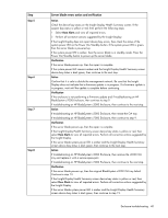
For the steps in this table, use the following definitions for all variables: • Standby Onboard Administrator = Suspect OA #Y • Y = Original bay location for the standby module • Second module = Suspect OA #X • X = Original bay location of the active module Step Server blade errors action and verification Step 1 Step 2 Step 3 Step 4 Action Confirm that the Insight Display is operating properly. Check that the Insight Display Health Summary screen device bay status is dark green. Verification If the Insight Display is not operating, then check that the enclosure is powered up. If the enclosure is powered up and the Onboard Administrator health LED is on, then see "Troubleshooting the Insight Display (on page 16)." If the Insight Display Health Summary screen device bay status is black, then continue to the next step. If the Insight Display Health Summary screen device bay status is yellow or red, then select View Alert to obtain the corrective action. If the Insight Display Health Summary screen device bay status is dark green, then continue to step 4. Action Remove the server blade and examine the signal and power connectors for damage. Verification If connector damage is visible, then dispose of the damaged server blade. Never install the damaged server blade in an enclosure. Continue to the next step. If the signal and power connectors are not damaged, then continue to the next step. Action Visually examine the suspect midplane assembly signal and power connectors in the suspect bay. Verification If the midplane assembly connectors for the suspect device bay are not damaged, then continue to the next step. If connector damage is visible, then the midplane failed. Contact an authorized service provider to complete the midplane assembly replacement (on page 69). Never install a device into the device bay with the damaged connector until the midplane assembly is replaced. Action Reseat the suspect server blade. Verification If the server blade powers up, then the repair is complete. If the server blade does not power up, then continue to the next step. Enclosure troubleshooting 39
-
 1
1 -
2
-
3
-
4
-
5
-
6
-
7
-
8
-
9
-
10
-
11
-
12
-
13
-
14
-
15
-
16
-
17
-
18
-
19
-
20
-
21
-
22
-
23
-
24
-
25
-
26
-
27
-
28
-
29
-
30
-
31
-
32
-
33
-
 34
34 -
 35
35 -
 36
36 -
 37
37 -
 38
38 -
 39
39 -
 40
40 -
 41
41 -
 42
42 -
 43
43 -
 44
44 -
45
-
46
-
47
-
48
-
49
-
50
-
51
-
52
-
53
-
54
-
55
-
56
-
57
-
58
-
59
-
60
-
61
-
62
-
63
-
64
-
65
-
66
-
67
-
68
-
69
-
70
-
71
-
72
-
73
-
74
-
75
-
76
-
77
-
78
-
79
-
80
-
81
-
82
-
83
-
84
-
85
-
86
-
87
-
88
-
89
-
90
-
91
-
92
-
93
-
94
-
95
-
96
-
97
-
98
-
99
-
100
-
101
-
102
-
103
-
104
-
105
-
106
 |
 |
