Panasonic WJHD500A WJHD500A User Guide - Page 18
Alarm Port Connection, Control, Alarm
 |
View all Panasonic WJHD500A manuals
Add to My Manuals
Save this manual to your list of manuals |
Page 18 highlights
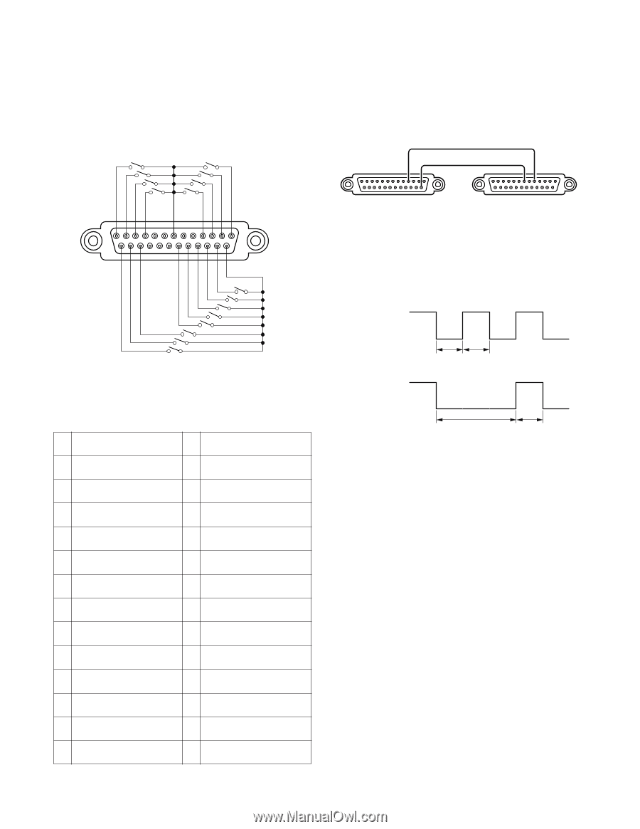
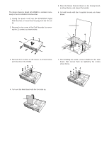
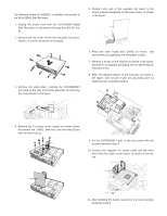
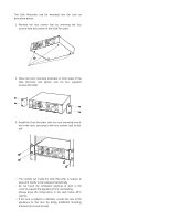
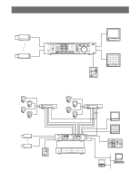
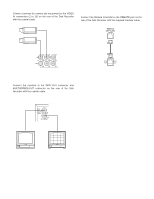
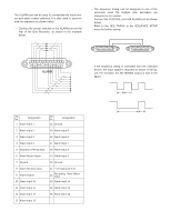
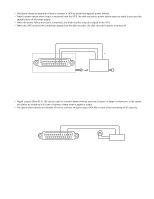
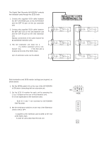
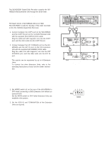
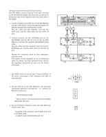
s Alarm Port Connection The ALARM port can be used for connecting the alarm sensor and alarm control switches. It is also used to synchronize the sequence as shown below. • Connect the sensor switches to the ALARM port on the rear of the Disk Recorder, as shown in the example below. 13 1 25 ALARM 14 Pin No. Designation 1 Alarm Input 1 Pin No. Designation 14 Ground 2 Alarm Input 2 15 Alarm Input 5 3 Alarm Input 3 16 Alarm Input 6 4 Alarm Input 4 17 Alarm Input 7 5 Sequence Timing Input 18 Alarm Input 8 6 Alarm Reset Output 19 Alarm Input 9 7 Ground 20 Ground 8 Alarm Recover Input 9 Alarm Output 10 Alarm Input 10 21 +5 V Output (0.2 A) 22 Recording Timer Select Input 23 Alarm Input 14 11 Alarm Input 11 24 Alarm Input 15 12 Alarm Input 12 25 Alarm Input 16 13 Alarm Input 13 • The sequence timing can be assigned to one of the recorders when the multiple Disk Recorders are equipped in the system. Connect the CONTROL port and ALARM port as shown below. Refer to the SEQ TIMING in the SEQUENCE SETUP menu for further setting. Sequence Timing Output Ground 4 Sequence Timing Input Ground 75 15 CONTROL WJ-HD500A (1st) ALARM WJ-HD500A (2nd) If the sequence timing is controlled from the outboard device, the input signal is required as shown in the figure. For example, the WJ-HD500A output is also in the figure. input WJ-HD500A output 100 ms 100 ms 500 ms 100 ms 18
-
 1
1 -
2
-
3
-
4
-
5
-
6
-
7
-
8
-
9
-
10
-
11
-
12
-
 13
13 -
 14
14 -
 15
15 -
 16
16 -
 17
17 -
 18
18 -
 19
19 -
 20
20 -
 21
21 -
 22
22 -
 23
23 -
24
-
25
-
26
-
27
-
28
-
29
-
30
-
31
-
32
-
33
-
34
-
35
-
36
-
37
-
38
-
39
-
40
-
41
-
42
-
43
-
44
-
45
-
46
-
47
-
48
-
49
-
50
-
51
-
52
-
53
-
54
-
55
-
56
-
57
-
58
-
59
-
60
-
61
-
62
-
63
-
64
-
65
-
66
-
67
-
68
-
69
-
70
-
71
-
72
-
73
-
74
-
75
-
76
-
77
-
78
-
79
-
80
-
81
-
82
-
83
-
84
-
85
-
86
-
87
-
88
-
89
-
90
-
91
-
92
-
93
-
94
-
95
-
96
-
97
-
98
-
99
-
100
-
101
-
102
 |
 |