Panasonic WJHD500A WJHD500A User Guide - Page 25
CONNECTION WITH THE PC, Serial Port Connection, 100BASE-T Port Connection
 |
View all Panasonic WJHD500A manuals
Add to My Manuals
Save this manual to your list of manuals |
Page 25 highlights
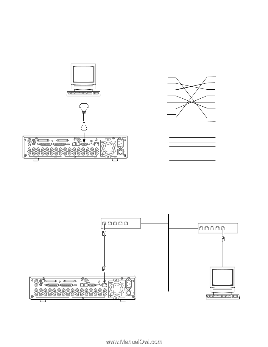
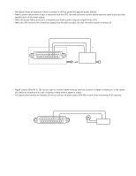
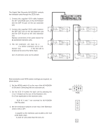
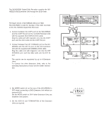
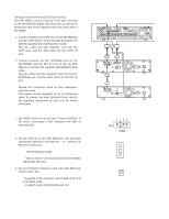
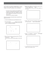
s Connection with the PC There are two options to communicate with the PC, the first is using Serial Port and the second is via Ethernet, when the specified Network Board is installed in the Disk Recorder. q Serial Port Connection The SERIAL Port on the rear of the Disk Recorder conforms to RS-232C, and it can communicate with the PC by connecting as shown in the figure. Personal Computer D-sub9 or D-sub25 D-sub9 IN SPOT OUT EXT STORAGE COPY DATA OUT MULTISCREENOUT AUDIO CONTROL ALARM MODE 16 15 14 13 12 11 10 9 8 7 6 IN OUT 16 15 14 13 12 11 10 9 8 7 6 VIDEO GEN-LOCK OUT REMOTE(WV-CU50) SERIAL SIGNAL GND 10/100BASE-T 5 4 3 2 1 5 4 3 2 1 Digital Disk Recorder AC IN ON OFF POWER WJ-HD500A DB9 1 2 3 4 5 6 7 8 WJ-HD500A DB9 2 (RXD) 3 (TXD) 4 (ER) 5 (GND) 6 (DR) 7 (RTS) 8 (CTS) PC DB9 1 2 3 4 5 6 7 8 PC DB25 2 (TXD) 3 (RXD) 6 (DR) 7 (GND) 20 (ER) 5 (CTS) 4 (RTS) q 10/100BASE-T Port Connection If the optional Network Board is installed in the WJ-HD500A Disk Recorder, it is enabled control from the PC via Ethernet. Shown in the figure is an example for connection. LAN Hub Hub 10/100BASE-T Cable (Locally Procured) IN SPOT OUT EXT STORAGE COPY DATA OUT MULTISCREENOUT AUDIO CONTROL ALARM MODE 16 15 14 13 12 11 10 9 8 7 6 IN OUT 16 15 14 13 12 11 10 9 8 7 6 VIDEO GEN-LOCK OUT REMOTE(WV-CU50) SERIAL SIGNAL GND 10/100BASE-T 5 4 3 2 1 5 4 3 2 1 Digital Disk Recorder AC IN ON OFF POWER Personal Computer 25
-
 1
1 -
2
-
3
-
4
-
5
-
6
-
7
-
8
-
9
-
10
-
11
-
12
-
13
-
14
-
15
-
16
-
17
-
18
-
19
-
 20
20 -
 21
21 -
 22
22 -
 23
23 -
 24
24 -
 25
25 -
 26
26 -
 27
27 -
 28
28 -
 29
29 -
 30
30 -
31
-
32
-
33
-
34
-
35
-
36
-
37
-
38
-
39
-
40
-
41
-
42
-
43
-
44
-
45
-
46
-
47
-
48
-
49
-
50
-
51
-
52
-
53
-
54
-
55
-
56
-
57
-
58
-
59
-
60
-
61
-
62
-
63
-
64
-
65
-
66
-
67
-
68
-
69
-
70
-
71
-
72
-
73
-
74
-
75
-
76
-
77
-
78
-
79
-
80
-
81
-
82
-
83
-
84
-
85
-
86
-
87
-
88
-
89
-
90
-
91
-
92
-
93
-
94
-
95
-
96
-
97
-
98
-
99
-
100
-
101
-
102
 |
 |