Panasonic WJHD500A WJHD500A User Guide - Page 20
Connection with the Uninterrupted Power Supply UPS, Connection with CONTROL output
 |
View all Panasonic WJHD500A manuals
Add to My Manuals
Save this manual to your list of manuals |
Page 20 highlights
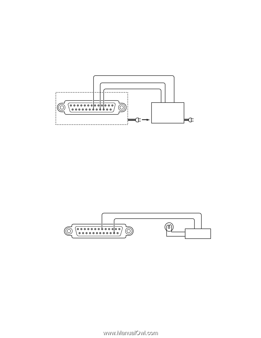
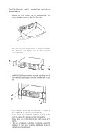
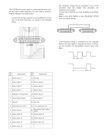
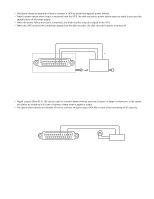
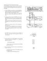
s Connection with the Uninterrupted Power Supply (UPS) • The figure shows an example of how to connect a UPS as protection against power failures. • When a power failure detect input is received from the UPS, the disk recorder's power failure process starts to process this signal to turn off its power supply. • When the power failure process is completed, the disk recorder outputs a signal to the UPS. • When the UPS receives the completion signal from the disk recorder, the disk recorder's power is turned off Disk Recorder WJ-HD500A Power Failure Process Completion Output Power Failure Detect Input Ground (19) (17) (16) UPS Shut Down Line Fail signal (Normally Open) Common CBefore connecting the UPS, refer to the manual of your UPS. CONTROL Uninterrupted Power Supply Power Cable to AC outlet s Connection with CONTROL output • Signal outputs (Pins #1-6, 18) can be used to connect alarm devices such as a buzzer or lamp to inform you of the operation status by sounding a buzzer or lighting a lamp when a signal is output. • The figure below shows an example of how to connect an alarm output (Pin #6) to warn of low remaining HDD capacity. (Remaining HDD Capacity Alarm Output) (6) (15) Ground Alarm Device CONTROL Input/Output Relay, etc. 20
-
 1
1 -
2
-
3
-
4
-
5
-
6
-
7
-
8
-
9
-
10
-
11
-
12
-
13
-
14
-
 15
15 -
 16
16 -
 17
17 -
 18
18 -
 19
19 -
 20
20 -
 21
21 -
 22
22 -
 23
23 -
 24
24 -
 25
25 -
26
-
27
-
28
-
29
-
30
-
31
-
32
-
33
-
34
-
35
-
36
-
37
-
38
-
39
-
40
-
41
-
42
-
43
-
44
-
45
-
46
-
47
-
48
-
49
-
50
-
51
-
52
-
53
-
54
-
55
-
56
-
57
-
58
-
59
-
60
-
61
-
62
-
63
-
64
-
65
-
66
-
67
-
68
-
69
-
70
-
71
-
72
-
73
-
74
-
75
-
76
-
77
-
78
-
79
-
80
-
81
-
82
-
83
-
84
-
85
-
86
-
87
-
88
-
89
-
90
-
91
-
92
-
93
-
94
-
95
-
96
-
97
-
98
-
99
-
100
-
101
-
102
 |
 |