Panasonic WJHD500A WJHD500A User Guide - Page 9
ALARM, Video Input Connectors VIDEO IN 1 - 16
 |
View all Panasonic WJHD500A manuals
Add to My Manuals
Save this manual to your list of manuals |
Page 9 highlights
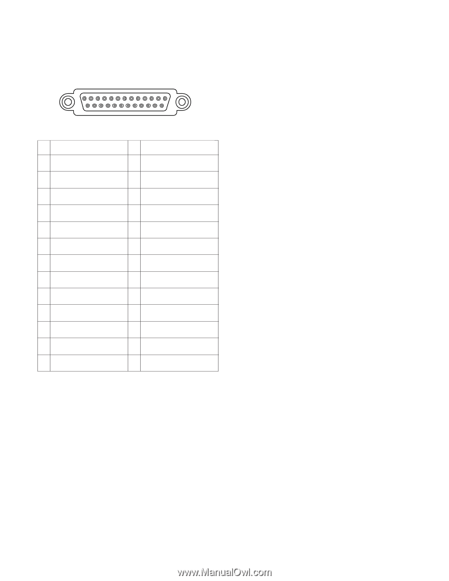
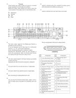
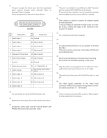
$7 Alarm Port (ALARM) This port accepts the alarm input from the associated alarm sensors through either Normally Open or Normally Closed contacts. The pin assignment of the port is shown below. 13 1 25 ALARM 14 Pin No. Designation 1 Alarm Input 1 Pin No. Designation 14 Ground 2 Alarm Input 2 15 Alarm Input 5 3 Alarm Input 3 16 Alarm Input 6 4 Alarm Input 4 17 Alarm Input 7 5 Sequence Timing Input 18 Alarm Input 8 6 Alarm Reset Output 19 Alarm Input 9 7 Ground 20 Ground 8 Alarm Recover Input 9 Alarm Output 10 Alarm Input 10 21 +5 V Output (0.2 A) 22 Recording Timer Select Input 23 Alarm Input 14 11 Alarm Input 11 24 Alarm Input 15 12 Alarm Input 12 25 Alarm Input 16 13 Alarm Input 13 $8 Copy Port (COPY) For connecting the optional DVD Extension Unit. $9 Mode Selector (MODE) Selects data termination for PS•Data system expansion. %0 Data Port (DATA) Exchanges control data with the external device with PS•Data (Panasonic Security Data) mode. %1 Remote Port [REMOTE (WV-CU50)] This port is provided for controlling the Disk Recorder with the optional WV-CU50 Remote Controller. To connect to the controller, use a 6-conductor modular cable supplied as an accessory with the controller. %2 Gen-lock Output Connector (GEN-LOCK OUT) This connector is used to connect an external system for synchronization. To record images at maximum recording rate, for example 60 fps, connect this output to the cameras to synchronize the system. %3 Serial Port (SERIAL) For connecting a Personal Computer. %4 Signal Ground Terminal (SIGNAL GND) %5 10/100BASE-T Port (Optional) An optional Network Board can be installed in the Disk Recorder. This port is used to exchange control data with Ethernet via an Ethernet Hub. %6 Cooling Fan Prevents the temperature of the Recorder from rising. Do not block the ventilation opening on the cover. %7 AC Inlet Socket (AC IN) Plug the power cord (supplied as a standard accessory) into this socket and connect it to an AC outlet. %8 Power Switch (POWER ON/OFF) This switch turns the power of the Disk Recorder on and off. %9 Video Output Connectors (VIDEO OUT 1 - 16) The video signal connected to the Video Input Connector (VIDEO IN) is looped through these connectors with an automatic 75 Ω termination. ^0 Video Input Connectors (VIDEO IN 1 - 16) These connectors accept either a color or B/W composite video signal from the camera. 9
-
 1
1 -
2
-
3
-
 4
4 -
 5
5 -
 6
6 -
 7
7 -
 8
8 -
 9
9 -
 10
10 -
 11
11 -
 12
12 -
 13
13 -
 14
14 -
15
-
16
-
17
-
18
-
19
-
20
-
21
-
22
-
23
-
24
-
25
-
26
-
27
-
28
-
29
-
30
-
31
-
32
-
33
-
34
-
35
-
36
-
37
-
38
-
39
-
40
-
41
-
42
-
43
-
44
-
45
-
46
-
47
-
48
-
49
-
50
-
51
-
52
-
53
-
54
-
55
-
56
-
57
-
58
-
59
-
60
-
61
-
62
-
63
-
64
-
65
-
66
-
67
-
68
-
69
-
70
-
71
-
72
-
73
-
74
-
75
-
76
-
77
-
78
-
79
-
80
-
81
-
82
-
83
-
84
-
85
-
86
-
87
-
88
-
89
-
90
-
91
-
92
-
93
-
94
-
95
-
96
-
97
-
98
-
99
-
100
-
101
-
102
 |
 |