Panasonic WJHD500A WJHD500A User Guide - Page 86
Alarm Recording, Alarm Recording for Manual and Power-on Recording
 |
View all Panasonic WJHD500A manuals
Add to My Manuals
Save this manual to your list of manuals |
Page 86 highlights
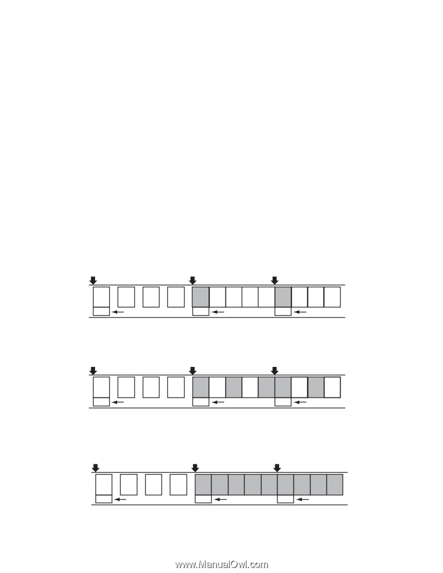
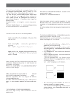
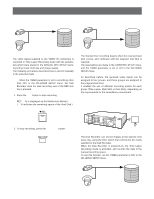
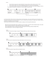
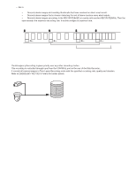
Notes: • When the TIMER parameter is set to EXT in the setup menu for Power-on Recording, the Internal Timer Recording is disabled. • Make sure to keep the POWER switch on the rear of the Disk Recorder set to ON. s Alarm Recording The Disk Recorder activates the recording alarm status within the specified recording mode, when an externally connected alarm sensor is turned on, or when the installed Video Motion Detector (optional) is activated. The alarm recording mode is determined by the setup in the WJ-HD500 SETUP menu. Described below is an alarm recording mode for each recording mentioned above. Note: The received alarm is ignored when the Disk Recorder is recording images in the Emergency Recording. (the alarm log is stored in the ERROR REPORT table.) q Alarm Recording for Manual and Power-on Recording The Disk Recorder records an alarm status based on the setup made in the MANUAL REC SETUP menu of the WJ-HD500 SETUP menu. It records the images as shown below in Time Lapse Recording mode with the specified recording rate, quality and duration. The recording pattern varies according to the setting for the Dynamic Recording (DYNAMIC REC) parameter. • Set to OFF Records all input images in sequence starting from video input which have activated alarm. Start Alarm 2 in Alarm 3 in C1 C2 C3 C4 C2 C3 C4 C5 C6 C3 C4 C5 C6 T Thumbnail T Thumbnail T Thumbnail • Set to ALM-PRI Records the alarm-activated input images preferentially over other video inputs. Start Alarm 4 in Alarm 15 in C1 C2 C3 C4 C4 C1 C4 C2 C4 C15 C1 C4 C2 T Thumbnail T Thumbnail T Thumbnail • Set to ALM-ONLY Records the particular images which have activated the alarm. Start Alarm 4 in Alarm 15 in C1 C2 C3 C4 C4 C4 C4 C4 C4 C15 C15 C15 C15 T Thumbnail T Thumbnail T Thumbnail 89
-
 1
1 -
2
-
3
-
4
-
5
-
6
-
7
-
8
-
9
-
10
-
11
-
12
-
13
-
14
-
15
-
16
-
17
-
18
-
19
-
20
-
21
-
22
-
23
-
24
-
25
-
26
-
27
-
28
-
29
-
30
-
31
-
32
-
33
-
34
-
35
-
36
-
37
-
38
-
39
-
40
-
41
-
42
-
43
-
44
-
45
-
46
-
47
-
48
-
49
-
50
-
51
-
52
-
53
-
54
-
55
-
56
-
57
-
58
-
59
-
60
-
61
-
62
-
63
-
64
-
65
-
66
-
67
-
68
-
69
-
70
-
71
-
72
-
73
-
74
-
75
-
76
-
77
-
78
-
79
-
80
-
 81
81 -
 82
82 -
 83
83 -
 84
84 -
 85
85 -
 86
86 -
 87
87 -
 88
88 -
 89
89 -
 90
90 -
 91
91 -
92
-
93
-
94
-
95
-
96
-
97
-
98
-
99
-
100
-
101
-
102
 |
 |