Panasonic WJHD500A WJHD500A User Guide - Page 24
Connection To Ps-data Compatible Equipment, Data Setup Menu.
 |
View all Panasonic WJHD500A manuals
Add to My Manuals
Save this manual to your list of manuals |
Page 24 highlights
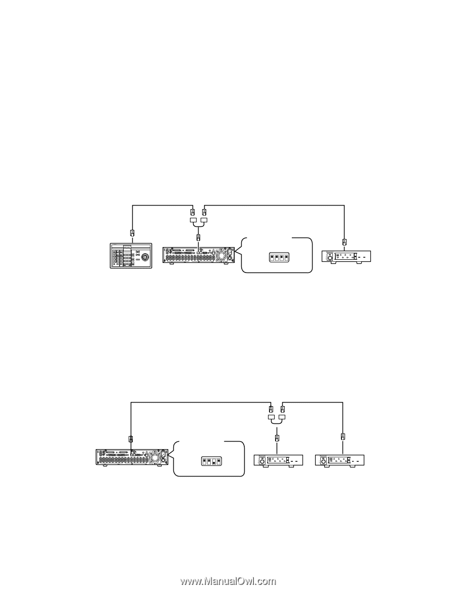
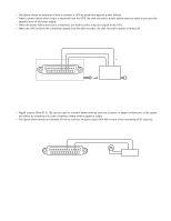
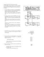
s Connection to PS •Data Compatible Equipment Note the following when connecting the Disk Recorder to equipment with PS•Data capability. q Connect the controller and PS •Data equipment at the ends of the PS •Data line. w Set the termination to ON for the units at both ends of the PS •Data line. Use the MODE selector on the rear of the WJ-HD500A Disk Recorder to set the termination. e Use the optional RS-485 cable for connection. Note: To be able to use PS •Data mode, the communication functions need to be set up in the PS •Data SETUP menu. q MODE Selector Setting • Set DIP switch 4 of the MODE selector as follows for data termination. ON: If the disk recorder is connected at the end of the PS •Data line. OFF: If the Disk Recorder is not connected at the end of the PS •Data line. Example: RS-485 Cable RS-485 Cable System Controller System Controller Termination : ON IN SPOT OUT EXT STORAGE COPY DATA OUT MULTISCREENOUT AUDIO CONTROL ALARM MODE 16 15 14 13 12 11 10 9 8 7 6 IN OUT 16 15 14 13 12 11 10 9 8 7 6 VIDEO GEN-LOCK OUT REMOTE(WV-CU50) SERIAL SIGNAL GND 10/100BASE-T 5 4 3 2 1 5 4 3 2 1 Disk Recorder AC IN ON OFF POWER ↑ MODE Selector (3 : OFF, 4 : OFF) ON 1234 POWER ON OFF 456 UNIT 901 1 ALARM RESET SUSPEND SET UP SET ESC ALARM ALARM SUSPEND 2 3 4 Data Multiplex Unit WJ-MP204 Data Multiplex Unit Termination : ON • If the optional WJ-HDB502 Network Board is installed as a controller in the Disk Recorder, the system can be controlled from a PC through the Disk Recorder. Set DIP switch 3 of the MODE selector as follows for data termination. ON: If the Network Board is connected at the end of the PS •Data line. OFF: If the Network Board is not connected at the end of the PS •Data line. For a system that has no system controller and is controlled through the Disk Recorder, for example, set DIP switch 3 of the MODE selector to ON position. RS-485 Cable RS-485 Cable 78 78 78 23 23 23 IN SPOT OUT EXT STORAGE COPY DATA OUT MULTISCREENOUT AUDIO CONTROL ALARM MODE 16 15 14 13 12 11 10 9 8 7 6 IN OUT 16 15 14 13 12 11 10 9 8 7 6 VIDEO GEN-LOCK OUT REMOTE(WV-CU50) SERIAL SIGNAL GND 10/100BASE-T 5 4 3 2 1 5 4 3 2 1 Disk Recorder AC IN ON OFF POWER ↑ MODE Selector (3 : ON, 4 : OFF) ON 1234 POWER ON OFF 456 UNIT 901 1 ALARM RESET SUSPEND SET UP SET ESC ALARM ALARM SUSPEND 2 3 4 Data Multiplex Unit WJ-MP204 Data Multiplex Unit Termination : OFF POWER ON OFF 456 UNIT 901 1 ALARM RESET SUSPEND SET UP SET ESC ALARM ALARM SUSPEND 2 3 4 Data Multiplex Unit WJ-MP204 Data Multiplex Unit Termination : ON Note: If the system has a system controller, set DIP switch 3 to OFF position. 24
-
 1
1 -
2
-
3
-
4
-
5
-
6
-
7
-
8
-
9
-
10
-
11
-
12
-
13
-
14
-
15
-
16
-
17
-
18
-
 19
19 -
 20
20 -
 21
21 -
 22
22 -
 23
23 -
 24
24 -
 25
25 -
 26
26 -
 27
27 -
 28
28 -
 29
29 -
30
-
31
-
32
-
33
-
34
-
35
-
36
-
37
-
38
-
39
-
40
-
41
-
42
-
43
-
44
-
45
-
46
-
47
-
48
-
49
-
50
-
51
-
52
-
53
-
54
-
55
-
56
-
57
-
58
-
59
-
60
-
61
-
62
-
63
-
64
-
65
-
66
-
67
-
68
-
69
-
70
-
71
-
72
-
73
-
74
-
75
-
76
-
77
-
78
-
79
-
80
-
81
-
82
-
83
-
84
-
85
-
86
-
87
-
88
-
89
-
90
-
91
-
92
-
93
-
94
-
95
-
96
-
97
-
98
-
99
-
100
-
101
-
102
 |
 |