Panasonic WJHD500A WJHD500A User Guide - Page 8
Rear View, Control
 |
View all Panasonic WJHD500A manuals
Add to My Manuals
Save this manual to your list of manuals |
Page 8 highlights
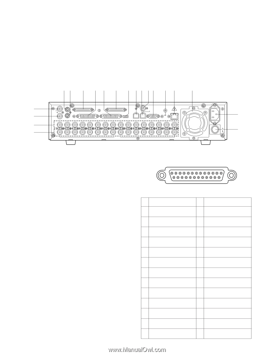
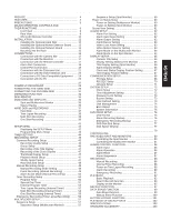
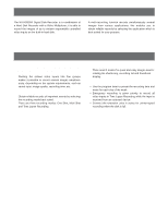
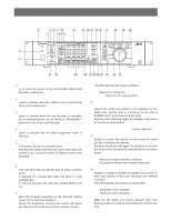
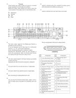
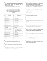
@9 Direction Buttons (CDA B) These buttons are used to select an area for a zoomed image displayed on the Multiscreen Monitor. During the setup, these buttons are used to move the cursor position in the setup menu of the Disk Recorder. C: Downward D: Upward A: Left B: Right #0 Full Indicator (FULL) Lights to indicate when the available recording space of the Disk Recorder (HDD) is running low. #1 Hard Disk Drive Indicator (HDD) Lights to indicate when the Hard Disk is activated. s Rear View $3 $4 $5 $6 $7 $8 $9 %0 %1 %2%3 %4 %5 %6 $2 $1 ^0 %9 IN SPOT OUT EXT STORAGE COPY DATA OUT MULTISCREENOUT AUDIO CONTROL ALARM MODE 16 15 14 13 12 11 10 9 8 7 6 IN OUT 16 15 14 13 12 11 10 9 8 7 6 VIDEO GEN-LOCK OUT REMOTE(WV-CU50) SERIAL SIGNAL GND 10/100BASE-T 5 4 3 2 1 5 4 3 2 1 AC IN ON OFF POWER %7 %8 $1 Multiscreen Output Connector (MULTISCREEN OUT) The video output signal for the Multiscreen Monitor is provided via this connector. It can be displayed as the video input in a multiscreen mode (4, 7, 9, 10, 13,16 screen segments). It also displays the Recorder's playback images. Pressing the SETUP/ESC button for two seconds or more will automatically select the Multiscreen Monitor and display the Disk Recorder's Setup menu. $2 Spot Output Connector (SPOT OUT) The video output signal for the Spot Monitor is provided via this connector. Displaying the Disk Recorder's playback is disabled. $3 Audio Input Connector (AUDIO IN) For audio input from an external device, if applicable. $4 Audio Output Connector (AUDIO OUT) For audio output to an external device, if applicable. $5 Extension Storage Port (EXT STORAGE) For connecting the optional Extension Unit. $6 Control Port (CONTROL) The port has the functions listed below. Make connections to these pins as needed for operating your system. 8 The pin assignment of the port is shown below. 13 1 25 CONTROL 14 Pin No. Designation 1 Group Recording Output Pin No. Designation 14 Disk Recorder Error Output 2 Manual Recording Output 15 Ground 3 Emergency Recording Output 16 Ground 4 Sequence Timing Output 17 Power Failure Detect Input 5 DVD Remain Space Output 6 HDD Remain Space Output 7 Thermal Error Input (Extension 1) 8 Thermal Error Input (Extension 2) 9 Thermal Error Input (Extension 3) 10 Thermal Error Input (Extension 4) 11 Thermal Error Input (Extension 5) 12 Thermal Error Input (Extension 6) 13 Thermal Error Input (DVD Unit) 18 Power Failure Proceeding Output 19 Power Failure Process Completion Output 20 Ground 21 Emergency Recording Input 22 Time Adjustment Output 23 Daylight Savings Select 24 Time Adjustment Input 25 Ground
-
 1
1 -
2
-
 3
3 -
 4
4 -
 5
5 -
 6
6 -
 7
7 -
 8
8 -
 9
9 -
 10
10 -
 11
11 -
 12
12 -
 13
13 -
14
-
15
-
16
-
17
-
18
-
19
-
20
-
21
-
22
-
23
-
24
-
25
-
26
-
27
-
28
-
29
-
30
-
31
-
32
-
33
-
34
-
35
-
36
-
37
-
38
-
39
-
40
-
41
-
42
-
43
-
44
-
45
-
46
-
47
-
48
-
49
-
50
-
51
-
52
-
53
-
54
-
55
-
56
-
57
-
58
-
59
-
60
-
61
-
62
-
63
-
64
-
65
-
66
-
67
-
68
-
69
-
70
-
71
-
72
-
73
-
74
-
75
-
76
-
77
-
78
-
79
-
80
-
81
-
82
-
83
-
84
-
85
-
86
-
87
-
88
-
89
-
90
-
91
-
92
-
93
-
94
-
95
-
96
-
97
-
98
-
99
-
100
-
101
-
102
 |
 |