Panasonic WJHD500A WJHD500A User Guide - Page 19
Control Port Connection
 |
View all Panasonic WJHD500A manuals
Add to My Manuals
Save this manual to your list of manuals |
Page 19 highlights
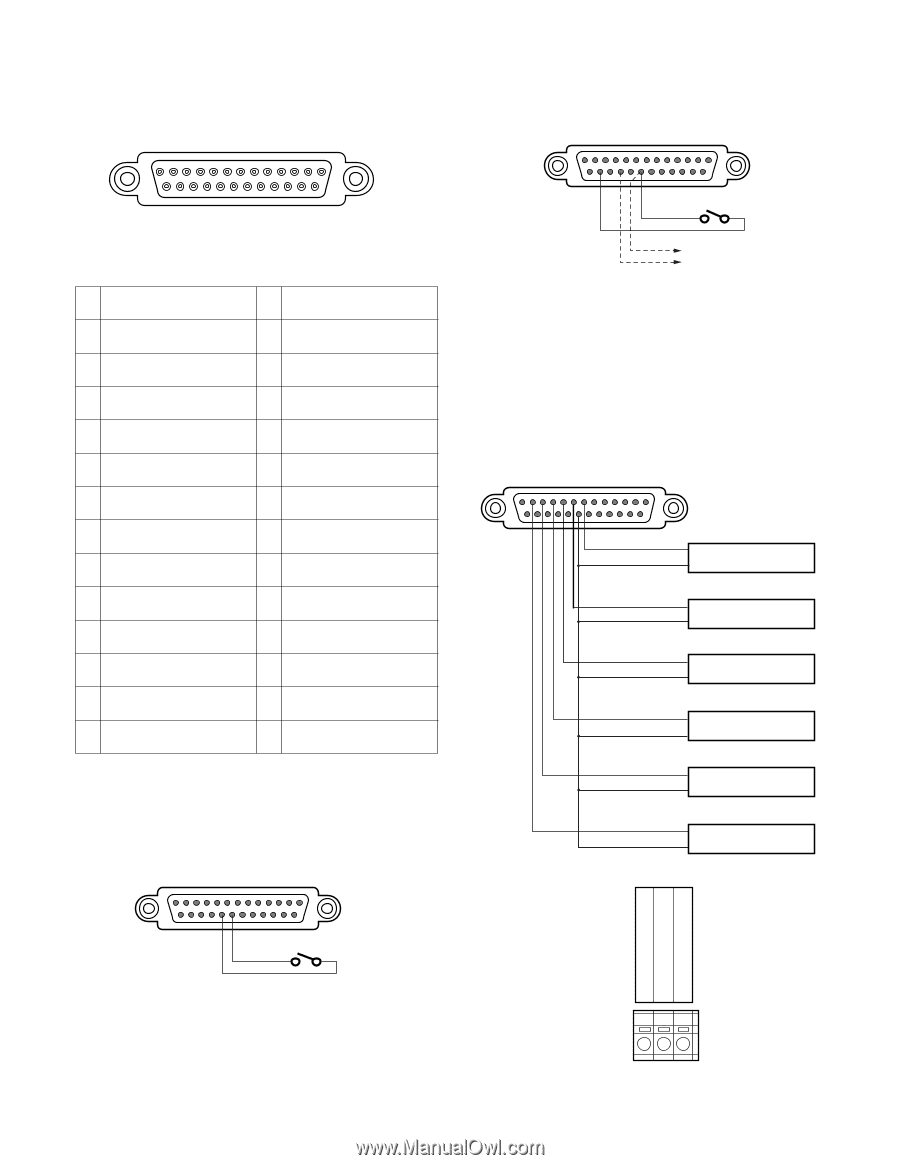
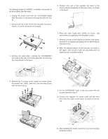
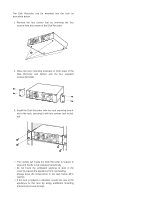
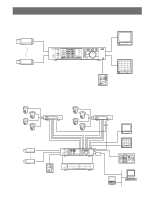
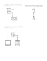
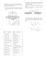
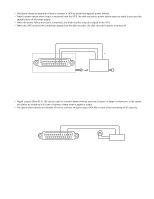
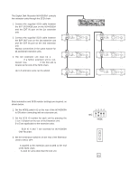
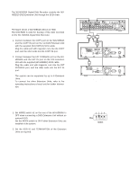
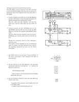
s Control Port Connection The CONTROL port can be used for controlling the system with the outboard device as shown below. 13 1 25 CONTROL 14 Pin No. Designation 1 Group Recording Output Pin No. Designation 14 Disk Recorder Error Output 2 Manual Recording Output 15 Ground 3 Emergency Recording Output 16 Ground 4 Sequence Timing Output 17 Power Failure Detect Input 5 DVD Remain Space Output 6 HDD Remain Space Output 7 Thermal Error Input (Extension 1) 8 Thermal Error Input (Extension 2) 9 Thermal Error Input (Extension 3) 10 Thermal Error Input (Extension 4) 11 Thermal Error Input (Extension 5) 12 Thermal Error Input (Extension 6) 13 Thermal Error Input (DVD Unit) 18 Power Failure Proceeding Output 19 Power Failure Process Completion Output 20 Ground 21 Emergency Recording Input 22 Time Adjustment Output 23 Daylight Savings Select 24 Time Adjustment Input 25 Ground • Emergency Recording can be enabled receiving the input from the connected external device. WJ-HD500A CONTROL Port 13 1 25 21 20 14 • Time adjustment can be enabled connecting with the external device as shown below. WJ-HD500A CONTROL Port 13 1 25 24 20 14 Time Adjustment Output • The Extension Units are installed in the system for extending its disk capacity. Connect each thermal error output from the Extension Units with the CONTROL Port on the rear of the WJHD500A Disk Recorder as shown below. The WJ-HD500A will display the warning for thermal error on the monitor. WJ-HD500A CONTROL Port 13 121110 9 8 7 1 25 14 Extension Unit #1 Thermal Error Out 20 G Extension Unit #2 Thermal Error Out G Extension Unit #3 Thermal Error Out G Extension Unit #4 Thermal Error Out G Extension Unit #5 Thermal Error Out G Extension Unit #6 Thermal Error Out G Terminal board on the Extension Unit G THERMAL ERROR OUT NC 19
-
 1
1 -
2
-
3
-
4
-
5
-
6
-
7
-
8
-
9
-
10
-
11
-
12
-
13
-
 14
14 -
 15
15 -
 16
16 -
 17
17 -
 18
18 -
 19
19 -
 20
20 -
 21
21 -
 22
22 -
 23
23 -
 24
24 -
25
-
26
-
27
-
28
-
29
-
30
-
31
-
32
-
33
-
34
-
35
-
36
-
37
-
38
-
39
-
40
-
41
-
42
-
43
-
44
-
45
-
46
-
47
-
48
-
49
-
50
-
51
-
52
-
53
-
54
-
55
-
56
-
57
-
58
-
59
-
60
-
61
-
62
-
63
-
64
-
65
-
66
-
67
-
68
-
69
-
70
-
71
-
72
-
73
-
74
-
75
-
76
-
77
-
78
-
79
-
80
-
81
-
82
-
83
-
84
-
85
-
86
-
87
-
88
-
89
-
90
-
91
-
92
-
93
-
94
-
95
-
96
-
97
-
98
-
99
-
100
-
101
-
102
 |
 |