Dell PowerEdge T410 Hardware Owner's Manual - Page 102
Optical and Tape Drives, Removing an Optical or a Tape Drive
 |
View all Dell PowerEdge T410 manuals
Add to My Manuals
Save this manual to your list of manuals |
Page 102 highlights
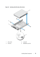
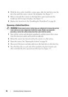
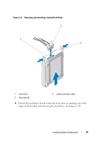
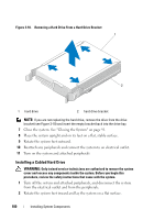
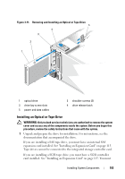
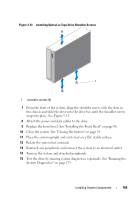
Optical and Tape Drives The 5.25-inch drive bays at the front of your system provide support for an optical drive and either an optional tape drive or a second optical drive. Removing an Optical or a Tape Drive WARNING: Only trained service technicians are authorized to remove the system cover and access any of the components inside the system. Before you begin this procedure, review the safety instructions that came with the system. 1 Turn off the system, including any attached peripherals, and disconnect the system from its electrical outlet. 2 Remove the front bezel. See "Removing the Front Bezel" on page 85. 3 Rotate the system feet inward and lay the system on a flat surface. 4 Open the system. See "Opening the System" on page 90. 5 Disconnect the power and data cables from the back of the drive. See Figure 3-12. 6 Slide the drive release latch in the direction of the arrow to release the shoulder screw and then slide the drive out of the bay. See Figure 3-12 7 If you are installing another drive in the bay, see "Installing an Optical or Tape Drive" on page 103. If the drive is being permanently removed: a Install an EMI filler into the empty drive bay. See "Installing an EMI Filler" on page 89. b Install a front bezel insert in the front bezel. See "Installing the Front Bezel Insert" on page 88. 8 Close the system. See "Closing the System" on page 91. 9 Place the system upright and on its feet on a flat, stable surface. 10 Rotate the system feet outward. 11 Replace the front bezel. See "Installing the Front Bezel" on page 86. 12 Reattach any peripherals and connect the system to an electrical outlet. 13 Turn on the system and attached peripherals. 102 Installing System Components
-
 1
1 -
2
-
3
-
4
-
5
-
6
-
7
-
8
-
9
-
10
-
11
-
12
-
13
-
14
-
15
-
16
-
17
-
18
-
19
-
20
-
21
-
22
-
23
-
24
-
25
-
26
-
27
-
28
-
29
-
30
-
31
-
32
-
33
-
34
-
35
-
36
-
37
-
38
-
39
-
40
-
41
-
42
-
43
-
44
-
45
-
46
-
47
-
48
-
49
-
50
-
51
-
52
-
53
-
54
-
55
-
56
-
57
-
58
-
59
-
60
-
61
-
62
-
63
-
64
-
65
-
66
-
67
-
68
-
69
-
70
-
71
-
72
-
73
-
74
-
75
-
76
-
77
-
78
-
79
-
80
-
81
-
82
-
83
-
84
-
85
-
86
-
87
-
88
-
89
-
90
-
91
-
92
-
93
-
94
-
95
-
96
-
 97
97 -
 98
98 -
 99
99 -
 100
100 -
 101
101 -
 102
102 -
 103
103 -
 104
104 -
 105
105 -
 106
106 -
 107
107 -
108
-
109
-
110
-
111
-
112
-
113
-
114
-
115
-
116
-
117
-
118
-
119
-
120
-
121
-
122
-
123
-
124
-
125
-
126
-
127
-
128
-
129
-
130
-
131
-
132
-
133
-
134
-
135
-
136
-
137
-
138
-
139
-
140
-
141
-
142
-
143
-
144
-
145
-
146
-
147
-
148
-
149
-
150
-
151
-
152
-
153
-
154
-
155
-
156
-
157
-
158
-
159
-
160
-
161
-
162
-
163
-
164
-
165
-
166
-
167
-
168
-
169
-
170
-
171
-
172
-
173
-
174
-
175
-
176
-
177
-
178
-
179
-
180
-
181
-
182
-
183
-
184
-
185
-
186
-
187
-
188
-
189
-
190
-
191
-
192
-
193
-
194
-
195
-
196
-
197
-
198
-
199
-
200
-
201
-
202
-
203
-
204
 |
 |