Dell PowerEdge T410 Hardware Owner's Manual - Page 153
Installing the System Board, Replace the system fan. See Installing the System Fan
 |
View all Dell PowerEdge T410 manuals
Add to My Manuals
Save this manual to your list of manuals |
Page 153 highlights
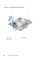
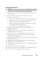
Installing the System Board WARNING: Only trained service technicians are authorized to remove the system cover and access any of the components inside the system. Before you begin this procedure, review the safety instructions that came with the system. 1 Unpack the new system board and remove the label that is located on the processor shield. 2 Remove the labels and affix them on the front of the chassis. 3 To replace the system board: a Grip the system board by holding the touch point and the captive screw. b Align the securing slots on the system board with the tabs on the chassis and lower the system board into the chassis. c Slide the system board towards the back of the system, inserting the connectors into the cutouts in the chassis. d Using a Phillips screwdriver, tighten the captive screw. 4 If applicable, replace the SAS backplane. See "Installing the SAS Backplane" on page 147. 5 Replace heatsinks, processors, and heatsink blanks (if applicable). See "Installing a Processor" on page 138. 6 Replace the system fan. See "Installing the System Fan" on page 135. 7 Replace all the memory modules and memory blanks. See "Installing Memory Modules" on page 110. 8 If applicable, replace the iDRAC6 Express card. See "Installing an iDRAC6 Express Card" on page 127. 9 If applicable, replace the iDRAC6 Enterprise card. See "Installing an iDRAC6 Enterprise Card" on page 129. 10 If applicable, replace all the expansion cards. See "Installing an Expansion Card" on page 115. 11 Connect all the cables to the system board. 12 Replace the cooling shroud. See "Installing the Cooling Shroud" on page 93. 13 Close the system. See "Closing the System" on page 91. Installing System Components 153
-
 1
1 -
2
-
3
-
4
-
5
-
6
-
7
-
8
-
9
-
10
-
11
-
12
-
13
-
14
-
15
-
16
-
17
-
18
-
19
-
20
-
21
-
22
-
23
-
24
-
25
-
26
-
27
-
28
-
29
-
30
-
31
-
32
-
33
-
34
-
35
-
36
-
37
-
38
-
39
-
40
-
41
-
42
-
43
-
44
-
45
-
46
-
47
-
48
-
49
-
50
-
51
-
52
-
53
-
54
-
55
-
56
-
57
-
58
-
59
-
60
-
61
-
62
-
63
-
64
-
65
-
66
-
67
-
68
-
69
-
70
-
71
-
72
-
73
-
74
-
75
-
76
-
77
-
78
-
79
-
80
-
81
-
82
-
83
-
84
-
85
-
86
-
87
-
88
-
89
-
90
-
91
-
92
-
93
-
94
-
95
-
96
-
97
-
98
-
99
-
100
-
101
-
102
-
103
-
104
-
105
-
106
-
107
-
108
-
109
-
110
-
111
-
112
-
113
-
114
-
115
-
116
-
117
-
118
-
119
-
120
-
121
-
122
-
123
-
124
-
125
-
126
-
127
-
128
-
129
-
130
-
131
-
132
-
133
-
134
-
135
-
136
-
137
-
138
-
139
-
140
-
141
-
142
-
143
-
144
-
145
-
146
-
147
-
 148
148 -
 149
149 -
 150
150 -
 151
151 -
 152
152 -
 153
153 -
 154
154 -
 155
155 -
 156
156 -
 157
157 -
 158
158 -
159
-
160
-
161
-
162
-
163
-
164
-
165
-
166
-
167
-
168
-
169
-
170
-
171
-
172
-
173
-
174
-
175
-
176
-
177
-
178
-
179
-
180
-
181
-
182
-
183
-
184
-
185
-
186
-
187
-
188
-
189
-
190
-
191
-
192
-
193
-
194
-
195
-
196
-
197
-
198
-
199
-
200
-
201
-
202
-
203
-
204
 |
 |