Dell PowerEdge T410 Hardware Owner's Manual - Page 142
Installing the Chassis Intrusion Switch, Control Panel Assembly (Service-Only Procedure)
 |
View all Dell PowerEdge T410 manuals
Add to My Manuals
Save this manual to your list of manuals |
Page 142 highlights
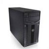
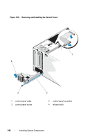
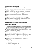
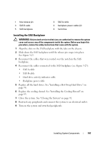
1 chassis intrusion switch 2 chassis intrusion switch cable 3 INTRUSION connector on the system board Installing the Chassis Intrusion Switch 1 Align the chassis intrusion switch with the securing bracket notch. See Figure 3-25. 2 Slide the switch into the securing bracket notch. See Figure 3-25. 3 Connect the chassis intrusion switch cable to the connector on the system board. 4 Close the system. See "Closing the System" on page 91. 5 Place the system upright and on its feet on a flat, stable surface. 6 Rotate the system feet outward. 7 Reattach any peripherals and connect the system to an electrical outlet. 8 Turn on the system and attached peripherals. Control Panel Assembly (Service-Only Procedure) Removing the Control Panel Assembly WARNING: Only trained service technicians are authorized to remove the system cover and access any of the components inside the system. Before you begin this procedure, review the safety instructions that came with the system. 1 Remove the bezel. See "Removing the Front Bezel" on page 85. 2 Turn off the system and attached peripherals, and disconnect the system from the electrical outlet and peripherals. 3 Rotate the system feet inward and lay the system on a flat surface. 4 Open the system. See "Opening the System" on page 90. CAUTION: Do not pull the cable to unseat the connector. Doing so can damage the cable. 142 Installing System Components
-
 1
1 -
2
-
3
-
4
-
5
-
6
-
7
-
8
-
9
-
10
-
11
-
12
-
13
-
14
-
15
-
16
-
17
-
18
-
19
-
20
-
21
-
22
-
23
-
24
-
25
-
26
-
27
-
28
-
29
-
30
-
31
-
32
-
33
-
34
-
35
-
36
-
37
-
38
-
39
-
40
-
41
-
42
-
43
-
44
-
45
-
46
-
47
-
48
-
49
-
50
-
51
-
52
-
53
-
54
-
55
-
56
-
57
-
58
-
59
-
60
-
61
-
62
-
63
-
64
-
65
-
66
-
67
-
68
-
69
-
70
-
71
-
72
-
73
-
74
-
75
-
76
-
77
-
78
-
79
-
80
-
81
-
82
-
83
-
84
-
85
-
86
-
87
-
88
-
89
-
90
-
91
-
92
-
93
-
94
-
95
-
96
-
97
-
98
-
99
-
100
-
101
-
102
-
103
-
104
-
105
-
106
-
107
-
108
-
109
-
110
-
111
-
112
-
113
-
114
-
115
-
116
-
117
-
118
-
119
-
120
-
121
-
122
-
123
-
124
-
125
-
126
-
127
-
128
-
129
-
130
-
131
-
132
-
133
-
134
-
135
-
136
-
 137
137 -
 138
138 -
 139
139 -
 140
140 -
 141
141 -
 142
142 -
 143
143 -
 144
144 -
 145
145 -
 146
146 -
 147
147 -
148
-
149
-
150
-
151
-
152
-
153
-
154
-
155
-
156
-
157
-
158
-
159
-
160
-
161
-
162
-
163
-
164
-
165
-
166
-
167
-
168
-
169
-
170
-
171
-
172
-
173
-
174
-
175
-
176
-
177
-
178
-
179
-
180
-
181
-
182
-
183
-
184
-
185
-
186
-
187
-
188
-
189
-
190
-
191
-
192
-
193
-
194
-
195
-
196
-
197
-
198
-
199
-
200
-
201
-
202
-
203
-
204
 |
 |