Dell PowerEdge T410 Hardware Owner's Manual - Page 105
Rotate the system feet outward
 |
View all Dell PowerEdge T410 manuals
Add to My Manuals
Save this manual to your list of manuals |
Page 105 highlights
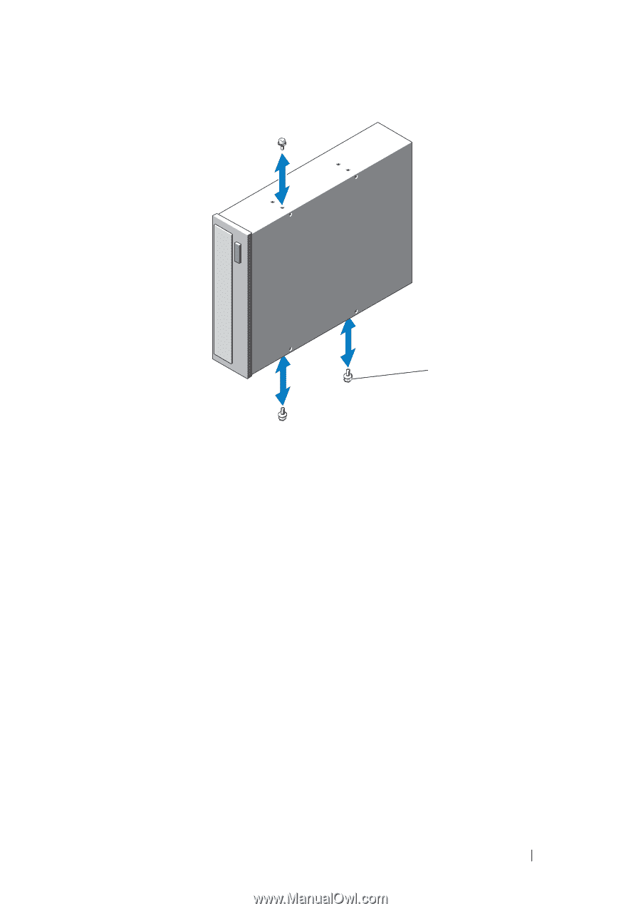
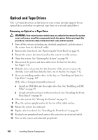
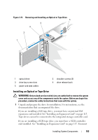
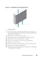
Figure 3-12. Installing Optical or Tape Drive Shoulder Screws 1 1 shoulder screws (3) 7 From the front of the system, align the shoulder screws with the slots in the chassis and slide the drive into the drive bay until the shoulder screws snap into place. See Figure 3-11. 8 Attach the power and data cables to the drive. 9 Replace the front bezel. See "Installing the Front Bezel" on page 86. 10 Close the system. See "Closing the System" on page 91. 11 Place the system upright and on its feet on a flat, stable surface. 12 Rotate the system feet outward. 13 Reattach any peripherals and connect the system to an electrical outlet. 14 Turn on the system and attached peripherals. 15 Test the drive by running system diagnostics (optional). See "Running the System Diagnostics" on page 173. Installing System Components 105
-
 1
1 -
2
-
3
-
4
-
5
-
6
-
7
-
8
-
9
-
10
-
11
-
12
-
13
-
14
-
15
-
16
-
17
-
18
-
19
-
20
-
21
-
22
-
23
-
24
-
25
-
26
-
27
-
28
-
29
-
30
-
31
-
32
-
33
-
34
-
35
-
36
-
37
-
38
-
39
-
40
-
41
-
42
-
43
-
44
-
45
-
46
-
47
-
48
-
49
-
50
-
51
-
52
-
53
-
54
-
55
-
56
-
57
-
58
-
59
-
60
-
61
-
62
-
63
-
64
-
65
-
66
-
67
-
68
-
69
-
70
-
71
-
72
-
73
-
74
-
75
-
76
-
77
-
78
-
79
-
80
-
81
-
82
-
83
-
84
-
85
-
86
-
87
-
88
-
89
-
90
-
91
-
92
-
93
-
94
-
95
-
96
-
97
-
98
-
99
-
 100
100 -
 101
101 -
 102
102 -
 103
103 -
 104
104 -
 105
105 -
 106
106 -
 107
107 -
 108
108 -
 109
109 -
 110
110 -
111
-
112
-
113
-
114
-
115
-
116
-
117
-
118
-
119
-
120
-
121
-
122
-
123
-
124
-
125
-
126
-
127
-
128
-
129
-
130
-
131
-
132
-
133
-
134
-
135
-
136
-
137
-
138
-
139
-
140
-
141
-
142
-
143
-
144
-
145
-
146
-
147
-
148
-
149
-
150
-
151
-
152
-
153
-
154
-
155
-
156
-
157
-
158
-
159
-
160
-
161
-
162
-
163
-
164
-
165
-
166
-
167
-
168
-
169
-
170
-
171
-
172
-
173
-
174
-
175
-
176
-
177
-
178
-
179
-
180
-
181
-
182
-
183
-
184
-
185
-
186
-
187
-
188
-
189
-
190
-
191
-
192
-
193
-
194
-
195
-
196
-
197
-
198
-
199
-
200
-
201
-
202
-
203
-
204
 |
 |