Dell PowerEdge T410 Hardware Owner's Manual - Page 125
Installing a Non-Redundant Power Supply, Internal USB Memory Key
 |
View all Dell PowerEdge T410 manuals
Add to My Manuals
Save this manual to your list of manuals |
Page 125 highlights
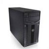
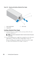
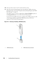
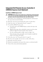
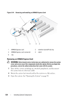
Installing a Non-Redundant Power Supply 1 Slide the power supply into the back of the chassis. 2 Replace the screws that secure the power supply to the chassis. See Figure 3-17. 3 Connect all the power cables to the system board and drives. Ensure that all the cables are routed properly to prevent the cables from being pinched or crimped. 4 Replace the cooling shroud. See "Installing the Cooling Shroud" on page 93. 5 Close the system. See "Closing the System" on page 91. 6 Place the system upright and on its feet on a flat, stable surface. 7 Rotate the system feet outward. 8 Reattach any peripherals and connect the system to an electrical outlet. 9 Turn on the system and attached peripherals. Internal USB Memory Key An optional USB memory key installed inside your system can be used as a boot device, security key, or mass storage device. WARNING: Only trained service technicians are authorized to remove the system cover and access any of the components inside the system. Before you begin this procedure, review the safety instructions that came with the system. 1 Turn off the system, including any attached peripherals, and disconnect the system from the electrical outlet. 2 Rotate the system feet inward and lay the system on a flat surface. 3 Open the system. See "Opening the System" on page 90. 4 Locate the USB connector on the system board. See Figure 6-1. 5 Insert the USB memory key into the USB connector. See Figure 3-18. 6 Close the system. See "Closing the System" on page 91. 7 Place the system upright and on its feet on a flat, stable surface. 8 Rotate the system feet outward. 9 Reattach any peripherals and connect the system to an electrical outlet. Installing System Components 125
-
 1
1 -
2
-
3
-
4
-
5
-
6
-
7
-
8
-
9
-
10
-
11
-
12
-
13
-
14
-
15
-
16
-
17
-
18
-
19
-
20
-
21
-
22
-
23
-
24
-
25
-
26
-
27
-
28
-
29
-
30
-
31
-
32
-
33
-
34
-
35
-
36
-
37
-
38
-
39
-
40
-
41
-
42
-
43
-
44
-
45
-
46
-
47
-
48
-
49
-
50
-
51
-
52
-
53
-
54
-
55
-
56
-
57
-
58
-
59
-
60
-
61
-
62
-
63
-
64
-
65
-
66
-
67
-
68
-
69
-
70
-
71
-
72
-
73
-
74
-
75
-
76
-
77
-
78
-
79
-
80
-
81
-
82
-
83
-
84
-
85
-
86
-
87
-
88
-
89
-
90
-
91
-
92
-
93
-
94
-
95
-
96
-
97
-
98
-
99
-
100
-
101
-
102
-
103
-
104
-
105
-
106
-
107
-
108
-
109
-
110
-
111
-
112
-
113
-
114
-
115
-
116
-
117
-
118
-
119
-
 120
120 -
 121
121 -
 122
122 -
 123
123 -
 124
124 -
 125
125 -
 126
126 -
 127
127 -
 128
128 -
 129
129 -
 130
130 -
131
-
132
-
133
-
134
-
135
-
136
-
137
-
138
-
139
-
140
-
141
-
142
-
143
-
144
-
145
-
146
-
147
-
148
-
149
-
150
-
151
-
152
-
153
-
154
-
155
-
156
-
157
-
158
-
159
-
160
-
161
-
162
-
163
-
164
-
165
-
166
-
167
-
168
-
169
-
170
-
171
-
172
-
173
-
174
-
175
-
176
-
177
-
178
-
179
-
180
-
181
-
182
-
183
-
184
-
185
-
186
-
187
-
188
-
189
-
190
-
191
-
192
-
193
-
194
-
195
-
196
-
197
-
198
-
199
-
200
-
201
-
202
-
203
-
204
 |
 |