Dell PowerEdge T410 Hardware Owner's Manual - Page 85
Front Bezel, Removing the Front Bezel - chassis
 |
View all Dell PowerEdge T410 manuals
Add to My Manuals
Save this manual to your list of manuals |
Page 85 highlights
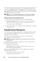
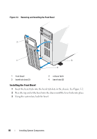
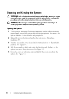
1 system cover 3 PCIe expansion card slots (5) 5 power supply bay 7 SAS backplane 9 SAS or SATA hard drives (up to 6) 11 tape drive (optional) 13 chassis intrusion switch 15 expansion card stabilizer 2 cooling shroud 4 system fan 6 heatsink and processor (1 or 2) 8 system feet (4) 10 control panel 12 optical drive (optional) 14 RAID battery (optional) Front Bezel NOTE: If you are removing or installing a hot-swappable hard drive, the system may remain turned on and in the upright position during removal of the front bezel. If you are removing or installing any other system component(s), the system should be turned off and placed in the orientation shown in Figure 3-1. Removing the Front Bezel 1 Using the system key, unlock the front bezel (if locked). 2 Slide the release latch in the direction of the arrow and rotate the top end of the bezel away from the chassis. 3 Lift the bezel away from the chassis. Installing System Components 85
-
 1
1 -
2
-
3
-
4
-
5
-
6
-
7
-
8
-
9
-
10
-
11
-
12
-
13
-
14
-
15
-
16
-
17
-
18
-
19
-
20
-
21
-
22
-
23
-
24
-
25
-
26
-
27
-
28
-
29
-
30
-
31
-
32
-
33
-
34
-
35
-
36
-
37
-
38
-
39
-
40
-
41
-
42
-
43
-
44
-
45
-
46
-
47
-
48
-
49
-
50
-
51
-
52
-
53
-
54
-
55
-
56
-
57
-
58
-
59
-
60
-
61
-
62
-
63
-
64
-
65
-
66
-
67
-
68
-
69
-
70
-
71
-
72
-
73
-
74
-
75
-
76
-
77
-
78
-
79
-
 80
80 -
 81
81 -
 82
82 -
 83
83 -
 84
84 -
 85
85 -
 86
86 -
 87
87 -
 88
88 -
 89
89 -
 90
90 -
91
-
92
-
93
-
94
-
95
-
96
-
97
-
98
-
99
-
100
-
101
-
102
-
103
-
104
-
105
-
106
-
107
-
108
-
109
-
110
-
111
-
112
-
113
-
114
-
115
-
116
-
117
-
118
-
119
-
120
-
121
-
122
-
123
-
124
-
125
-
126
-
127
-
128
-
129
-
130
-
131
-
132
-
133
-
134
-
135
-
136
-
137
-
138
-
139
-
140
-
141
-
142
-
143
-
144
-
145
-
146
-
147
-
148
-
149
-
150
-
151
-
152
-
153
-
154
-
155
-
156
-
157
-
158
-
159
-
160
-
161
-
162
-
163
-
164
-
165
-
166
-
167
-
168
-
169
-
170
-
171
-
172
-
173
-
174
-
175
-
176
-
177
-
178
-
179
-
180
-
181
-
182
-
183
-
184
-
185
-
186
-
187
-
188
-
189
-
190
-
191
-
192
-
193
-
194
-
195
-
196
-
197
-
198
-
199
-
200
-
201
-
202
-
203
-
204
 |
 |