Dell PowerEdge T410 Hardware Owner's Manual - Page 150
Installing the Power Distribution Board, System Board (Service-Only Procedure)
 |
View all Dell PowerEdge T410 manuals
Add to My Manuals
Save this manual to your list of manuals |
Page 150 highlights
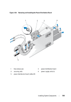
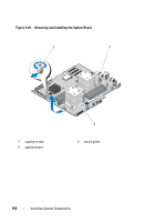
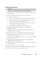
Installing the Power Distribution Board 1 Align the securing slots on the power distribution board with the tabs on the chassis. 2 Slide the board downwards until the blue release pin locks into place. 3 Connect all the power distribution board cables to the system board. 4 Replace the cooling shroud. See "Installing the Cooling Shroud" on page 93. 5 Replace the power supplies. See "Installing a Redundant Power Supply" on page 122. 6 Close the system. See "Closing the System" on page 91. 7 Place the system upright and on its feet on a flat, stable surface. 8 Rotate the system feet outward. 9 Reattach any peripherals and connect the system to an electrical outlet. 10 Turn on the system and attached peripherals. System Board (Service-Only Procedure) WARNING: The heat sink can get hot during operation. To avoid burns, ensure that the system has sufficient time to cool before removing the system board. CAUTION: If you are using the Trusted Platform Module (TPM) with an encryption program, you may be prompted to create a recovery key during system or program setup. Be sure to create and safely store this recovery key. If you ever need to replace the system board, you must supply the recovery key when you restart your system or program before you can access the encrypted data on your hard drive(s). Removing the System Board WARNING: Only trained service technicians are authorized to remove the system cover and access any of the components inside the system. Before you begin this procedure, review the safety instructions that came with the system. 1 Turn off the system, including any attached peripherals, and disconnect the system from the electrical outlet and peripherals. 2 Remove the front bezel. See "Removing the Front Bezel" on page 85. 3 Rotate the system feet inward and lay the system on a flat surface. 150 Installing System Components
-
 1
1 -
2
-
3
-
4
-
5
-
6
-
7
-
8
-
9
-
10
-
11
-
12
-
13
-
14
-
15
-
16
-
17
-
18
-
19
-
20
-
21
-
22
-
23
-
24
-
25
-
26
-
27
-
28
-
29
-
30
-
31
-
32
-
33
-
34
-
35
-
36
-
37
-
38
-
39
-
40
-
41
-
42
-
43
-
44
-
45
-
46
-
47
-
48
-
49
-
50
-
51
-
52
-
53
-
54
-
55
-
56
-
57
-
58
-
59
-
60
-
61
-
62
-
63
-
64
-
65
-
66
-
67
-
68
-
69
-
70
-
71
-
72
-
73
-
74
-
75
-
76
-
77
-
78
-
79
-
80
-
81
-
82
-
83
-
84
-
85
-
86
-
87
-
88
-
89
-
90
-
91
-
92
-
93
-
94
-
95
-
96
-
97
-
98
-
99
-
100
-
101
-
102
-
103
-
104
-
105
-
106
-
107
-
108
-
109
-
110
-
111
-
112
-
113
-
114
-
115
-
116
-
117
-
118
-
119
-
120
-
121
-
122
-
123
-
124
-
125
-
126
-
127
-
128
-
129
-
130
-
131
-
132
-
133
-
134
-
135
-
136
-
137
-
138
-
139
-
140
-
141
-
142
-
143
-
144
-
 145
145 -
 146
146 -
 147
147 -
 148
148 -
 149
149 -
 150
150 -
 151
151 -
 152
152 -
 153
153 -
 154
154 -
 155
155 -
156
-
157
-
158
-
159
-
160
-
161
-
162
-
163
-
164
-
165
-
166
-
167
-
168
-
169
-
170
-
171
-
172
-
173
-
174
-
175
-
176
-
177
-
178
-
179
-
180
-
181
-
182
-
183
-
184
-
185
-
186
-
187
-
188
-
189
-
190
-
191
-
192
-
193
-
194
-
195
-
196
-
197
-
198
-
199
-
200
-
201
-
202
-
203
-
204
 |
 |