Dell PowerEdge T410 Hardware Owner's Manual - Page 104
Remove the EMI filler. See Removing an EMI Filler
 |
View all Dell PowerEdge T410 manuals
Add to My Manuals
Save this manual to your list of manuals |
Page 104 highlights
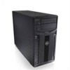
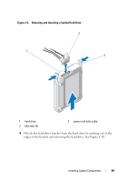
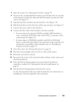
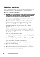
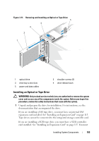
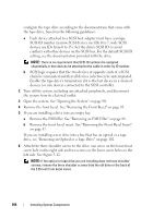
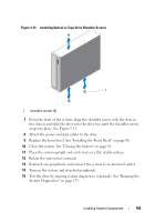
configure the tape drive according to the documentation that came with the tape drive, based on the following guidelines: a Each device attached to a SCSI host adapter must have a unique SCSI ID number (narrow SCSI devices use IDs 0 to 7; wide SCSI devices use IDs from 0 to 15). Set the drive's SCSI ID to avoid conflicts with other devices on the SCSI bus. For the default SCSI ID setting, see the documentation provided with the drive. NOTE: There is no requirement that SCSI ID numbers be assigned sequentially or that devices be attached to the cable in order by ID number. b SCSI logic requires that the two devices at opposite ends of a SCSI chain be terminated and that all devices in between be unterminated. Enable the tape drive's termination if it is the last device in a chain of devices (or sole device) connected to the SCSI controller. 2 Turn off the system, including any attached peripherals, and disconnect the system from its electrical outlet. 3 Open the system. See "Opening the System" on page 90. 4 Remove the front bezel. See "Removing the Front Bezel" on page 85. 5 If you are installing a drive into an empty bay: a Remove the EMI filler. See "Removing an EMI Filler" on page 88. b Remove the front bezel insert. See "Removing the Front Bezel Insert" on page 87. If you are installing a new drive into a bay that has an optical or a tape drive, see "Removing an Optical or a Tape Drive" on page 102. 6 Attach the three shoulder screws to the drive, one screw on the lower front screw hole on the right side and two screws on the lower screw holes on the left side. See Figure 3-12. NOTE: If the optical or tape drive you are installing does not have shoulder screws, remove the three shoulder screws from the old drive or the back of the 5.25-inch front bezel insert. 104 Installing System Components
-
 1
1 -
2
-
3
-
4
-
5
-
6
-
7
-
8
-
9
-
10
-
11
-
12
-
13
-
14
-
15
-
16
-
17
-
18
-
19
-
20
-
21
-
22
-
23
-
24
-
25
-
26
-
27
-
28
-
29
-
30
-
31
-
32
-
33
-
34
-
35
-
36
-
37
-
38
-
39
-
40
-
41
-
42
-
43
-
44
-
45
-
46
-
47
-
48
-
49
-
50
-
51
-
52
-
53
-
54
-
55
-
56
-
57
-
58
-
59
-
60
-
61
-
62
-
63
-
64
-
65
-
66
-
67
-
68
-
69
-
70
-
71
-
72
-
73
-
74
-
75
-
76
-
77
-
78
-
79
-
80
-
81
-
82
-
83
-
84
-
85
-
86
-
87
-
88
-
89
-
90
-
91
-
92
-
93
-
94
-
95
-
96
-
97
-
98
-
 99
99 -
 100
100 -
 101
101 -
 102
102 -
 103
103 -
 104
104 -
 105
105 -
 106
106 -
 107
107 -
 108
108 -
 109
109 -
110
-
111
-
112
-
113
-
114
-
115
-
116
-
117
-
118
-
119
-
120
-
121
-
122
-
123
-
124
-
125
-
126
-
127
-
128
-
129
-
130
-
131
-
132
-
133
-
134
-
135
-
136
-
137
-
138
-
139
-
140
-
141
-
142
-
143
-
144
-
145
-
146
-
147
-
148
-
149
-
150
-
151
-
152
-
153
-
154
-
155
-
156
-
157
-
158
-
159
-
160
-
161
-
162
-
163
-
164
-
165
-
166
-
167
-
168
-
169
-
170
-
171
-
172
-
173
-
174
-
175
-
176
-
177
-
178
-
179
-
180
-
181
-
182
-
183
-
184
-
185
-
186
-
187
-
188
-
189
-
190
-
191
-
192
-
193
-
194
-
195
-
196
-
197
-
198
-
199
-
200
-
201
-
202
-
203
-
204
 |
 |