Dell PowerEdge T410 Hardware Owner's Manual - Page 151
See SAS Backplane
 |
View all Dell PowerEdge T410 manuals
Add to My Manuals
Save this manual to your list of manuals |
Page 151 highlights
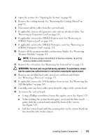
4 Open the system. See "Opening the System" on page 90. 5 Remove the cooling shroud. See "Removing the Cooling Shroud" on page 92. 6 Disconnect all the cables from the system board. 7 If applicable, remove all expansion cards and any attached cables. See "Removing an Expansion Card" on page 118. 8 If applicable, remove the iDRAC6 Express card. See "Removing an iDRAC6 Express Card" on page 128. 9 If applicable, remove the iDRAC6 Enterprise card. See "Removing an iDRAC6 Enterprise Card" on page 132. 10 Remove all the memory modules and memory blanks. See "Removing Memory Modules" on page 113. NOTE: To ensure proper reinstallation of memory modules, record the memory module socket locations. 11 Remove the system fan. See "Removing the System Fan" on page 133. WARNING: The heat sink can get hot during operation. To avoid burns, ensure that the system has sufficient time to cool before removing the system board. 12 Remove any installed heat sinks, processors and heat-sink blanks. See "Removing a Processor" on page 135. 13 If applicable, remove the SAS backplane from system. See "Removing the SAS Backplane" on page 145. 14 Carefully route any loose cables away from the edges of the system board. 15 To remove the system board: a Using a Phillips screwdriver, loosen the captive screw. See Figure 3-29. b While holding the system board captive screw and the blue touch point, slide the system board toward the front of the system. See Figure 3-29. c Lift the system board until the securing slots on the system board are free from the tabs on the chassis. Installing System Components 151
-
 1
1 -
2
-
3
-
4
-
5
-
6
-
7
-
8
-
9
-
10
-
11
-
12
-
13
-
14
-
15
-
16
-
17
-
18
-
19
-
20
-
21
-
22
-
23
-
24
-
25
-
26
-
27
-
28
-
29
-
30
-
31
-
32
-
33
-
34
-
35
-
36
-
37
-
38
-
39
-
40
-
41
-
42
-
43
-
44
-
45
-
46
-
47
-
48
-
49
-
50
-
51
-
52
-
53
-
54
-
55
-
56
-
57
-
58
-
59
-
60
-
61
-
62
-
63
-
64
-
65
-
66
-
67
-
68
-
69
-
70
-
71
-
72
-
73
-
74
-
75
-
76
-
77
-
78
-
79
-
80
-
81
-
82
-
83
-
84
-
85
-
86
-
87
-
88
-
89
-
90
-
91
-
92
-
93
-
94
-
95
-
96
-
97
-
98
-
99
-
100
-
101
-
102
-
103
-
104
-
105
-
106
-
107
-
108
-
109
-
110
-
111
-
112
-
113
-
114
-
115
-
116
-
117
-
118
-
119
-
120
-
121
-
122
-
123
-
124
-
125
-
126
-
127
-
128
-
129
-
130
-
131
-
132
-
133
-
134
-
135
-
136
-
137
-
138
-
139
-
140
-
141
-
142
-
143
-
144
-
145
-
 146
146 -
 147
147 -
 148
148 -
 149
149 -
 150
150 -
 151
151 -
 152
152 -
 153
153 -
 154
154 -
 155
155 -
 156
156 -
157
-
158
-
159
-
160
-
161
-
162
-
163
-
164
-
165
-
166
-
167
-
168
-
169
-
170
-
171
-
172
-
173
-
174
-
175
-
176
-
177
-
178
-
179
-
180
-
181
-
182
-
183
-
184
-
185
-
186
-
187
-
188
-
189
-
190
-
191
-
192
-
193
-
194
-
195
-
196
-
197
-
198
-
199
-
200
-
201
-
202
-
203
-
204
 |
 |