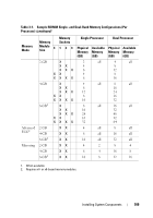
Dell PowerEdge T410 Hardware Owner's Manual - Page 111
Press out the ejectors on each end of the socket until the memory-module
 |
View all Dell PowerEdge T410 manuals
Add to My Manuals
Save this manual to your list of manuals |
Page 111 highlights
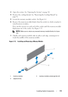
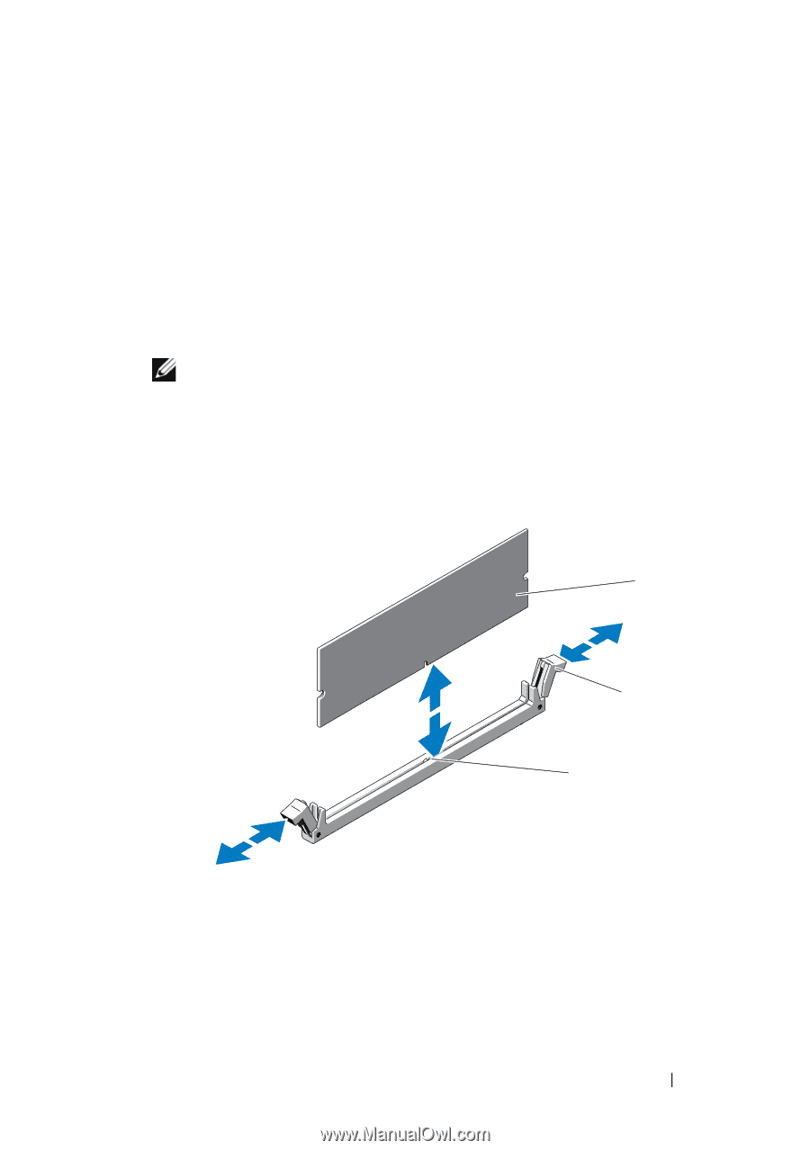
3 Open the system. See "Opening the System" on page 90. 4 Remove the cooling shroud. See "Removing the Cooling Shroud" on page 92. 5 Locate the memory module sockets. See Figure 6-1. 6 Remove the memory-module blanks from the sockets in which you plan to install memory modules: Press out the ejectors on each end of the socket until the memory-module blank pops out of the socket. See Figure 3-13. NOTE: Make sure to retain any removed memory-module blanks for future use. 7 Handle each memory module only on either card edge, ensuring not to touch the middle of the memory module. Figure 3-13. Installing and Removing a Memory Module 1 2 3 1 memory module 3 alignment key 2 memory module socket ejectors (2) Installing System Components 111
-
 1
1 -
2
-
3
-
4
-
5
-
6
-
7
-
8
-
9
-
10
-
11
-
12
-
13
-
14
-
15
-
16
-
17
-
18
-
19
-
20
-
21
-
22
-
23
-
24
-
25
-
26
-
27
-
28
-
29
-
30
-
31
-
32
-
33
-
34
-
35
-
36
-
37
-
38
-
39
-
40
-
41
-
42
-
43
-
44
-
45
-
46
-
47
-
48
-
49
-
50
-
51
-
52
-
53
-
54
-
55
-
56
-
57
-
58
-
59
-
60
-
61
-
62
-
63
-
64
-
65
-
66
-
67
-
68
-
69
-
70
-
71
-
72
-
73
-
74
-
75
-
76
-
77
-
78
-
79
-
80
-
81
-
82
-
83
-
84
-
85
-
86
-
87
-
88
-
89
-
90
-
91
-
92
-
93
-
94
-
95
-
96
-
97
-
98
-
99
-
100
-
101
-
102
-
103
-
104
-
105
-
 106
106 -
 107
107 -
 108
108 -
 109
109 -
 110
110 -
 111
111 -
 112
112 -
 113
113 -
 114
114 -
 115
115 -
 116
116 -
117
-
118
-
119
-
120
-
121
-
122
-
123
-
124
-
125
-
126
-
127
-
128
-
129
-
130
-
131
-
132
-
133
-
134
-
135
-
136
-
137
-
138
-
139
-
140
-
141
-
142
-
143
-
144
-
145
-
146
-
147
-
148
-
149
-
150
-
151
-
152
-
153
-
154
-
155
-
156
-
157
-
158
-
159
-
160
-
161
-
162
-
163
-
164
-
165
-
166
-
167
-
168
-
169
-
170
-
171
-
172
-
173
-
174
-
175
-
176
-
177
-
178
-
179
-
180
-
181
-
182
-
183
-
184
-
185
-
186
-
187
-
188
-
189
-
190
-
191
-
192
-
193
-
194
-
195
-
196
-
197
-
198
-
199
-
200
-
201
-
202
-
203
-
204
 |
 |
Installing System Components
111
3
Open the system. See "Opening the System" on page 90.
4
Remove the cooling shroud. See "Removing the Cooling Shroud" on
page 92.
5
Locate the memory module sockets. See Figure 6-1.
6
Remove the memory-module blanks from the sockets in which you plan to
install memory modules:
Press out the ejectors on each end of the socket until the memory-module
blank pops out of the socket. See Figure 3-13.
NOTE:
Make sure to retain any removed memory-module blanks for future
use.
7
Handle each memory module only on either card edge, ensuring not to
touch the middle of the memory module.
Figure 3-13.
Installing and Removing a Memory Module
1
memory module
2
memory module socket ejectors (2)
3
alignment key
2
1
3