Dell PowerEdge T430 Dell PowerEdge T430 Owners Manual - Page 130
Follow the same steps to remove the control panel in the rack-mode configuration., control panel cable
 |
View all Dell PowerEdge T430 manuals
Add to My Manuals
Save this manual to your list of manuals |
Page 130 highlights
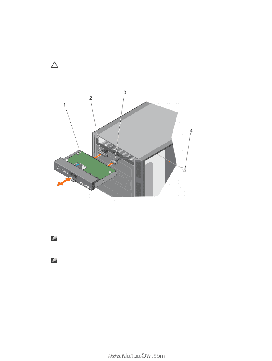
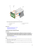
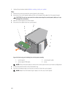
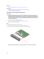
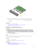
3. Follow the procedure listed in Before working inside your system. Steps 1. Remove the screw securing the control panel to the chassis. 2. Disconnect the control panel cable and the control panel USB cable from the system board. CAUTION: Do not use excessive force when removing the control panel cables as it can damage the connectors. 3. Slide the control panel out of the chassis. 4. Disconnect the cables from the control panel. Figure 56. Removing and installing the control panel assembly 1. control panel 3. control panel USB cable 2. control panel cable 4. screw NOTE: Follow the same steps to remove the control panel in the rack-mode configuration. 5. Locate and press the tabs on the information tag. 6. Push the information tag out of the slot to remove it from the control panel. NOTE: Retain the information tag to replace it in the new control panel. 130
-
 1
1 -
2
-
3
-
4
-
5
-
6
-
7
-
8
-
9
-
10
-
11
-
12
-
13
-
14
-
15
-
16
-
17
-
18
-
19
-
20
-
21
-
22
-
23
-
24
-
25
-
26
-
27
-
28
-
29
-
30
-
31
-
32
-
33
-
34
-
35
-
36
-
37
-
38
-
39
-
40
-
41
-
42
-
43
-
44
-
45
-
46
-
47
-
48
-
49
-
50
-
51
-
52
-
53
-
54
-
55
-
56
-
57
-
58
-
59
-
60
-
61
-
62
-
63
-
64
-
65
-
66
-
67
-
68
-
69
-
70
-
71
-
72
-
73
-
74
-
75
-
76
-
77
-
78
-
79
-
80
-
81
-
82
-
83
-
84
-
85
-
86
-
87
-
88
-
89
-
90
-
91
-
92
-
93
-
94
-
95
-
96
-
97
-
98
-
99
-
100
-
101
-
102
-
103
-
104
-
105
-
106
-
107
-
108
-
109
-
110
-
111
-
112
-
113
-
114
-
115
-
116
-
117
-
118
-
119
-
120
-
121
-
122
-
123
-
124
-
 125
125 -
 126
126 -
 127
127 -
 128
128 -
 129
129 -
 130
130 -
 131
131 -
 132
132 -
 133
133 -
 134
134 -
 135
135 -
136
-
137
-
138
-
139
-
140
-
141
-
142
-
143
-
144
-
145
-
146
-
147
-
148
-
149
-
150
-
151
-
152
-
153
-
154
-
155
-
156
-
157
-
158
-
159
-
160
-
161
-
162
-
163
-
164
-
165
-
166
-
167
-
168
-
169
-
170
-
171
-
172
-
173
-
174
-
175
-
176
-
177
-
178
-
179
 |
 |