Dell PowerEdge T430 Dell PowerEdge T430 Owners Manual - Page 75
Next steps, Related Links, connector on the PERC card
 |
View all Dell PowerEdge T430 manuals
Add to My Manuals
Save this manual to your list of manuals |
Page 75 highlights
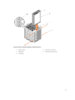
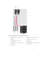
Figure 27. Cabling-Cabled hard-drives with a PERC card 1. front-panel HDD LED controller connector on the system board 3. SATA tape drive connector on system board 5. SAS connector on PERC card 7. front-panel HDD LED controller connector on the PERC card 9. tape drive 2. SATA optical drive connector on system board 4. system board 6. PERC card 8. hard drives 10. optical drive Next steps 1. Install the internal hard-drive bay into the chassis. 2. If disconnected, reconnect the power and data cable(s) to the remaining hard drive(s) in the internal hard-drive bay. Related Links Removing the internal hard-drive bay Installing a cabled hard drive 75
-
 1
1 -
2
-
3
-
4
-
5
-
6
-
7
-
8
-
9
-
10
-
11
-
12
-
13
-
14
-
15
-
16
-
17
-
18
-
19
-
20
-
21
-
22
-
23
-
24
-
25
-
26
-
27
-
28
-
29
-
30
-
31
-
32
-
33
-
34
-
35
-
36
-
37
-
38
-
39
-
40
-
41
-
42
-
43
-
44
-
45
-
46
-
47
-
48
-
49
-
50
-
51
-
52
-
53
-
54
-
55
-
56
-
57
-
58
-
59
-
60
-
61
-
62
-
63
-
64
-
65
-
66
-
67
-
68
-
69
-
 70
70 -
 71
71 -
 72
72 -
 73
73 -
 74
74 -
 75
75 -
 76
76 -
 77
77 -
 78
78 -
 79
79 -
 80
80 -
81
-
82
-
83
-
84
-
85
-
86
-
87
-
88
-
89
-
90
-
91
-
92
-
93
-
94
-
95
-
96
-
97
-
98
-
99
-
100
-
101
-
102
-
103
-
104
-
105
-
106
-
107
-
108
-
109
-
110
-
111
-
112
-
113
-
114
-
115
-
116
-
117
-
118
-
119
-
120
-
121
-
122
-
123
-
124
-
125
-
126
-
127
-
128
-
129
-
130
-
131
-
132
-
133
-
134
-
135
-
136
-
137
-
138
-
139
-
140
-
141
-
142
-
143
-
144
-
145
-
146
-
147
-
148
-
149
-
150
-
151
-
152
-
153
-
154
-
155
-
156
-
157
-
158
-
159
-
160
-
161
-
162
-
163
-
164
-
165
-
166
-
167
-
168
-
169
-
170
-
171
-
172
-
173
-
174
-
175
-
176
-
177
-
178
-
179
 |
 |
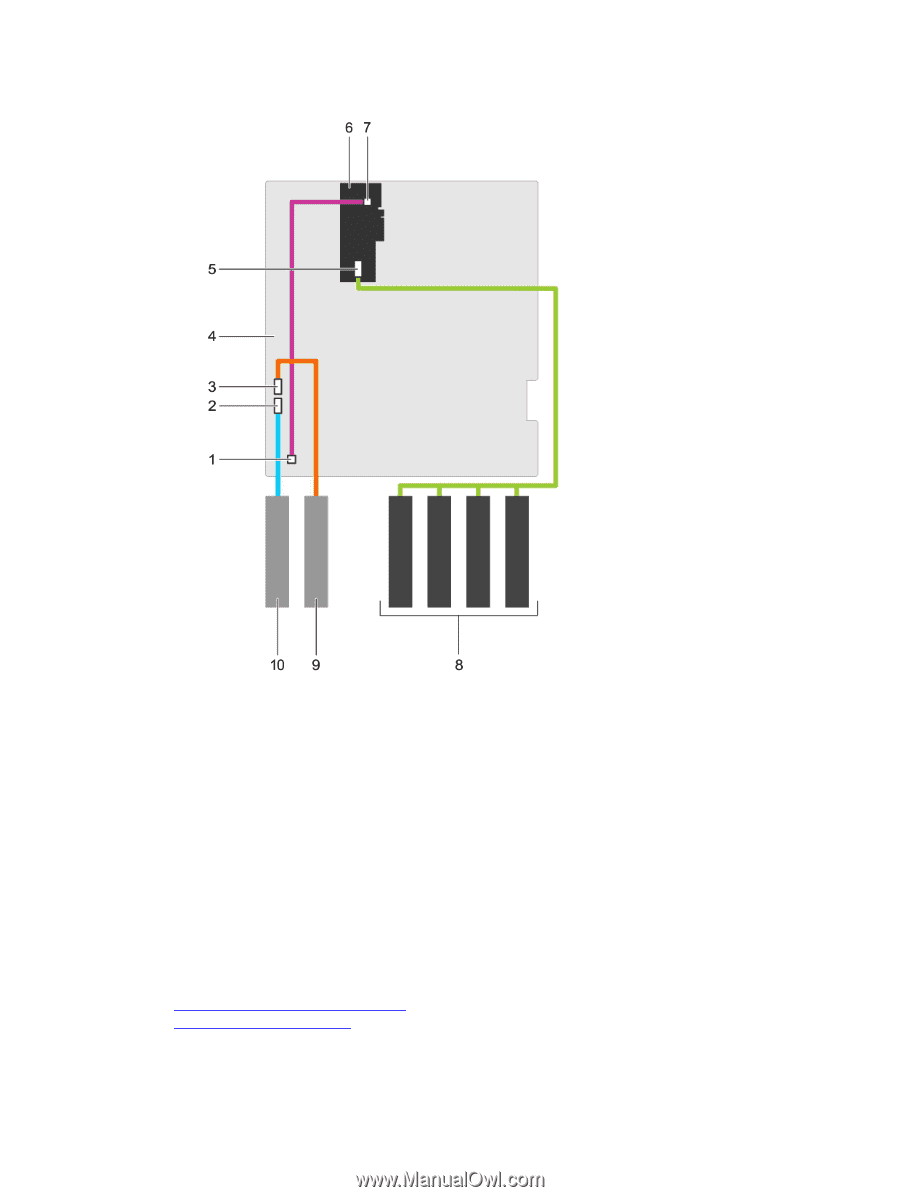
Figure 27. Cabling—Cabled hard-drives with a PERC card
1.
front-panel HDD LED controller
connector on the system board
2.
SATA optical drive connector on system
board
3.
SATA tape drive connector on system
board
4.
system board
5.
SAS connector on PERC card
6.
PERC card
7.
front-panel HDD LED controller
connector on the PERC card
8.
hard drives
9.
tape drive
10.
optical drive
Next steps
1.
Install the internal hard-drive bay into the chassis.
2.
If disconnected, reconnect the power and data cable(s) to the remaining hard drive(s) in the internal
hard-drive bay.
Related Links
Removing the internal hard-drive bay
Installing a cabled hard drive
75