Dell PowerEdge T430 Dell PowerEdge T430 Owners Manual - Page 150
Steps, Next steps, Install the three screws using a #2 Phillips screwdriver.
 |
View all Dell PowerEdge T430 manuals
Add to My Manuals
Save this manual to your list of manuals |
Page 150 highlights
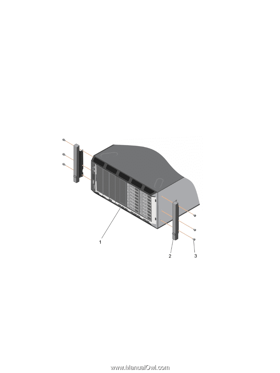
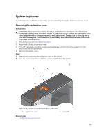
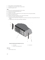
4. Lay the system on a flat and stable surface. 5. If installed, remove the system feet or caster wheels. 6. Remove the system cover. Steps 1. Remove the control panel assembly from the chassis. 2. Remove the control panel assembly cover. 3. Install the VGA module. 4. Install the control panel assembly cover for rack mode into the control panel assembly. 5. Remove the system top cover. 6. Install the control panel assembly for rack mode into the chassis. 7. To attach the rack ears, follow the steps below: a. Align the three screw holes on the right rack ear with the screw holes on the right side of the rack system. b. Install the three screws using a #2 Phillips screwdriver. Figure 68. Removing and installing the rack ears 1. front panel 3. screws for each rack ear (3) Next steps 1. Install the system cover. 2. rack ears (2) 150
-
 1
1 -
2
-
3
-
4
-
5
-
6
-
7
-
8
-
9
-
10
-
11
-
12
-
13
-
14
-
15
-
16
-
17
-
18
-
19
-
20
-
21
-
22
-
23
-
24
-
25
-
26
-
27
-
28
-
29
-
30
-
31
-
32
-
33
-
34
-
35
-
36
-
37
-
38
-
39
-
40
-
41
-
42
-
43
-
44
-
45
-
46
-
47
-
48
-
49
-
50
-
51
-
52
-
53
-
54
-
55
-
56
-
57
-
58
-
59
-
60
-
61
-
62
-
63
-
64
-
65
-
66
-
67
-
68
-
69
-
70
-
71
-
72
-
73
-
74
-
75
-
76
-
77
-
78
-
79
-
80
-
81
-
82
-
83
-
84
-
85
-
86
-
87
-
88
-
89
-
90
-
91
-
92
-
93
-
94
-
95
-
96
-
97
-
98
-
99
-
100
-
101
-
102
-
103
-
104
-
105
-
106
-
107
-
108
-
109
-
110
-
111
-
112
-
113
-
114
-
115
-
116
-
117
-
118
-
119
-
120
-
121
-
122
-
123
-
124
-
125
-
126
-
127
-
128
-
129
-
130
-
131
-
132
-
133
-
134
-
135
-
136
-
137
-
138
-
139
-
140
-
141
-
142
-
143
-
144
-
 145
145 -
 146
146 -
 147
147 -
 148
148 -
 149
149 -
 150
150 -
 151
151 -
 152
152 -
 153
153 -
 154
154 -
 155
155 -
156
-
157
-
158
-
159
-
160
-
161
-
162
-
163
-
164
-
165
-
166
-
167
-
168
-
169
-
170
-
171
-
172
-
173
-
174
-
175
-
176
-
177
-
178
-
179
 |
 |