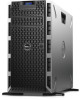
Dell PowerEdge T430 Dell PowerEdge T430 Owners Manual - Page 21
Two integrated 10/100/1000 Mbps NIC, One 450 W non-redundant
 |
View all Dell PowerEdge T430 manuals
Add to My Manuals
Save this manual to your list of manuals |
Page 21 highlights
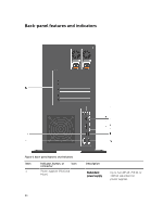
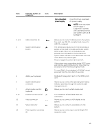
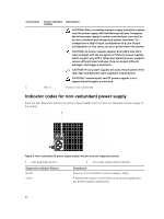
Item Indicator, button, or connector Icon 2, 6, 8 USB connectors (6) 3 System identification button 4 5 7 9, 12 10 11 13 iDRAC port (optional) System identification connector vFlash media card slot (optional) Ethernet connectors (2) Video connector Serial connector PCIe expansion card slots (6) Description Non-redundant power supply One 450 W non-redundant AC power supply. NOTE: Non-redundant power supply is supported in systems with cabled hard drives and systems with an x8 backplane. Allows you to connect USB devices to the system. Five ports are USB 2.0-compliant and one port is USB 3.0-compliant. The identification buttons on the front and back panels can be used to locate a particular system within a rack. When one of these buttons is pressed, the LCD panel on the front and the system status indicator on the back flash until one of the buttons is pressed again. Press to toggle the system ID on and off. If the system stops responding during POST, press and hold the system ID button for more than five seconds to enter the BIOS progress mode. To reset iDRAC (if not disabled in F2 iDRAC setup), press and hold for more than 15 seconds. Dedicated management port on the iDRAC ports card. Allows you to connect the optional system status indicator assembly through the optional cable management arm. Allows you to insert a vFlash media card. Two integrated 10/100/1000 Mbps NIC connectors. Allows you to connect a VGA display to the system. Allows you to connect a serial device to the system. Allows you to connect up to six full-height PCI expansion cards. 21
-
 1
1 -
2
-
3
-
4
-
5
-
6
-
7
-
8
-
9
-
10
-
11
-
12
-
13
-
14
-
15
-
 16
16 -
 17
17 -
 18
18 -
 19
19 -
 20
20 -
 21
21 -
 22
22 -
 23
23 -
 24
24 -
 25
25 -
 26
26 -
27
-
28
-
29
-
30
-
31
-
32
-
33
-
34
-
35
-
36
-
37
-
38
-
39
-
40
-
41
-
42
-
43
-
44
-
45
-
46
-
47
-
48
-
49
-
50
-
51
-
52
-
53
-
54
-
55
-
56
-
57
-
58
-
59
-
60
-
61
-
62
-
63
-
64
-
65
-
66
-
67
-
68
-
69
-
70
-
71
-
72
-
73
-
74
-
75
-
76
-
77
-
78
-
79
-
80
-
81
-
82
-
83
-
84
-
85
-
86
-
87
-
88
-
89
-
90
-
91
-
92
-
93
-
94
-
95
-
96
-
97
-
98
-
99
-
100
-
101
-
102
-
103
-
104
-
105
-
106
-
107
-
108
-
109
-
110
-
111
-
112
-
113
-
114
-
115
-
116
-
117
-
118
-
119
-
120
-
121
-
122
-
123
-
124
-
125
-
126
-
127
-
128
-
129
-
130
-
131
-
132
-
133
-
134
-
135
-
136
-
137
-
138
-
139
-
140
-
141
-
142
-
143
-
144
-
145
-
146
-
147
-
148
-
149
-
150
-
151
-
152
-
153
-
154
-
155
-
156
-
157
-
158
-
159
-
160
-
161
-
162
-
163
-
164
-
165
-
166
-
167
-
168
-
169
-
170
-
171
-
172
-
173
-
174
-
175
-
176
-
177
-
178
-
179
 |
 |