Dell PowerEdge T430 Dell PowerEdge T430 Owners Manual - Page 169
Advanced Management Enablement Adapter AMEA connector, Connector, Description
 |
View all Dell PowerEdge T430 manuals
Add to My Manuals
Save this manual to your list of manuals |
Page 169 highlights
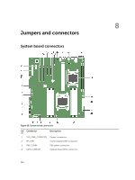
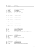
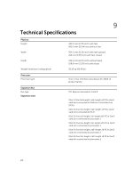
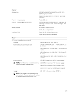
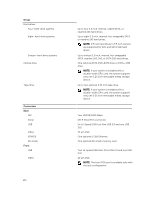
Ite Connector m 5 SATA_TBU 6 J_SATA_B 7 CTRL_PNL 8 J_SATA_A 9 INT_USB_3.0 10 TPM_MODULE 11 J_PSWD_NVRAM 12 SLOT1 PCIE_G2_X4 (PCH) 13 SLOT2 PCIE_G2_ X1 (PCH) 14 SLOT3 PCIE_G3_X16 (CPU1) 15 SLOT4 PCIE_G3_X16 (CPU1) 16 SLOT5 PCIE_G3_X8 (CPU2) 17 SLOT6 PCIE_G3_X8 (CPU2) 18 BATTERY 19 FAN1 20 FAN2 21 B1, B2 22 J_AMEA 23 B4, B3 24 CPU2 25 PWR_CONN_C (P3) 26 CPU1 27 IDSDM 28 INTRUSION 29 A1, A5, A2, A6 30 PWR_CONN_B (P2) 31 A8, A4, A7, A3 32 ACT_LED Description Tape drive SATA connector SATA connector B Control panel interface connector SATA connector A Internal USB connector Trusted Platform Module (TPM) connector See System Board Jumper Settings PCIe card connector 1 PCIe card connector 2 PCIe card connector 3 PCIe card connector 4 PCIe card connector 5 PCIe card connector 6 System battery Internal cooling fan connector External cooling fan connector Memory module sockets Advanced Management Enablement Adapter (AMEA) connector Memory module sockets Processor 2 CPU2 power connector Processor 1 Internal dual SD module connector Intrusion switch connector Memory module sockets CPU1 power connector Memory module sockets Front-panel hard-drive LED controller connector 169
-
 1
1 -
2
-
3
-
4
-
5
-
6
-
7
-
8
-
9
-
10
-
11
-
12
-
13
-
14
-
15
-
16
-
17
-
18
-
19
-
20
-
21
-
22
-
23
-
24
-
25
-
26
-
27
-
28
-
29
-
30
-
31
-
32
-
33
-
34
-
35
-
36
-
37
-
38
-
39
-
40
-
41
-
42
-
43
-
44
-
45
-
46
-
47
-
48
-
49
-
50
-
51
-
52
-
53
-
54
-
55
-
56
-
57
-
58
-
59
-
60
-
61
-
62
-
63
-
64
-
65
-
66
-
67
-
68
-
69
-
70
-
71
-
72
-
73
-
74
-
75
-
76
-
77
-
78
-
79
-
80
-
81
-
82
-
83
-
84
-
85
-
86
-
87
-
88
-
89
-
90
-
91
-
92
-
93
-
94
-
95
-
96
-
97
-
98
-
99
-
100
-
101
-
102
-
103
-
104
-
105
-
106
-
107
-
108
-
109
-
110
-
111
-
112
-
113
-
114
-
115
-
116
-
117
-
118
-
119
-
120
-
121
-
122
-
123
-
124
-
125
-
126
-
127
-
128
-
129
-
130
-
131
-
132
-
133
-
134
-
135
-
136
-
137
-
138
-
139
-
140
-
141
-
142
-
143
-
144
-
145
-
146
-
147
-
148
-
149
-
150
-
151
-
152
-
153
-
154
-
155
-
156
-
157
-
158
-
159
-
160
-
161
-
162
-
163
-
 164
164 -
 165
165 -
 166
166 -
 167
167 -
 168
168 -
 169
169 -
 170
170 -
 171
171 -
 172
172 -
 173
173 -
 174
174 -
175
-
176
-
177
-
178
-
179
 |
 |