Dell PowerEdge T430 Dell PowerEdge T430 Owners Manual - Page 54
Removing caster wheels, Related Links, Prerequisites, Steps
 |
View all Dell PowerEdge T430 manuals
Add to My Manuals
Save this manual to your list of manuals |
Page 54 highlights
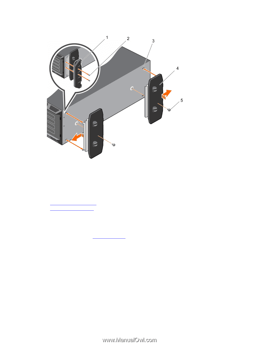
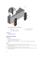
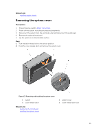
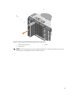
Figure 12. Removing and installing caster wheels 1. support unit 3. slot on base of the tower (4) 5. screw for wheel assembly (2) 2. screw for support unit (2) 4. wheel assembly unit (2) Related Links Removing the system feet Removing caster wheels Removing caster wheels Prerequisites 1. Ensure that you read the Safety instructions. 2. Keep the #2 Phillips screwdriver ready. 3. Lay the system on a flat and stable surface with the wheels extending beyond the edge of the surface. Steps 1. Remove the screw securing the front wheel unit to the base of the chassis. 2. Offset the front wheel unit slightly to the back of the system to release the retention hooks, and pull out the front wheel unit. 3. Remove the screw securing the back wheel unit to the base of the chassis. 4. Offset the back wheel unit slightly to the front of the system to release the retention hooks, and pull out the back wheel unit. 54
-
 1
1 -
2
-
3
-
4
-
5
-
6
-
7
-
8
-
9
-
10
-
11
-
12
-
13
-
14
-
15
-
16
-
17
-
18
-
19
-
20
-
21
-
22
-
23
-
24
-
25
-
26
-
27
-
28
-
29
-
30
-
31
-
32
-
33
-
34
-
35
-
36
-
37
-
38
-
39
-
40
-
41
-
42
-
43
-
44
-
45
-
46
-
47
-
48
-
 49
49 -
 50
50 -
 51
51 -
 52
52 -
 53
53 -
 54
54 -
 55
55 -
 56
56 -
 57
57 -
 58
58 -
 59
59 -
60
-
61
-
62
-
63
-
64
-
65
-
66
-
67
-
68
-
69
-
70
-
71
-
72
-
73
-
74
-
75
-
76
-
77
-
78
-
79
-
80
-
81
-
82
-
83
-
84
-
85
-
86
-
87
-
88
-
89
-
90
-
91
-
92
-
93
-
94
-
95
-
96
-
97
-
98
-
99
-
100
-
101
-
102
-
103
-
104
-
105
-
106
-
107
-
108
-
109
-
110
-
111
-
112
-
113
-
114
-
115
-
116
-
117
-
118
-
119
-
120
-
121
-
122
-
123
-
124
-
125
-
126
-
127
-
128
-
129
-
130
-
131
-
132
-
133
-
134
-
135
-
136
-
137
-
138
-
139
-
140
-
141
-
142
-
143
-
144
-
145
-
146
-
147
-
148
-
149
-
150
-
151
-
152
-
153
-
154
-
155
-
156
-
157
-
158
-
159
-
160
-
161
-
162
-
163
-
164
-
165
-
166
-
167
-
168
-
169
-
170
-
171
-
172
-
173
-
174
-
175
-
176
-
177
-
178
-
179
 |
 |