HP 2500c Service Manual - Page 126
Paper Paths and Components
 |
View all HP 2500c manuals
Add to My Manuals
Save this manual to your list of manuals |
Page 126 highlights
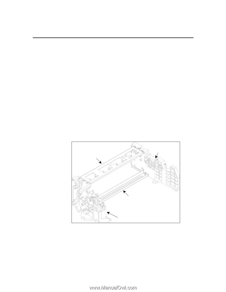
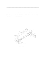
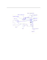
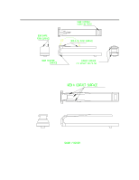
Paper Paths and Components Chassis The chassis structure consists of two high strength polymeric supports held together by two sheet metal tie bars (see figure below). The two tie bars are placed a distance apart to yield a high moment of inertia. This results in a structure of high rigidity in torsion and bending. Besides structural purposes, the lower tie bar is used to mount the paper trough and the higher tie bar to hold the upper paper guides. An open structure like this can accommodate flexibility in designing for removable trough from the back. Moreover, the modularity allows ease of assembly at the top level; the carriage system is mounted at the top and the dual bin is mounted at the bottom on the two supports. The primary datum of the system is on the supports, thus minimizing the tolerance stackup on critical subsystems like the drive, input and carriage. Polymeric material of the supports allows flexibility in complex designs to support these subsystems. . Upper tie bar Right support Lower tie bar Left support Chassis Structure 6-6 Functional Overview
-
 1
1 -
2
-
3
-
4
-
5
-
6
-
7
-
8
-
9
-
10
-
11
-
12
-
13
-
14
-
15
-
16
-
17
-
18
-
19
-
20
-
21
-
22
-
23
-
24
-
25
-
26
-
27
-
28
-
29
-
30
-
31
-
32
-
33
-
34
-
35
-
36
-
37
-
38
-
39
-
40
-
41
-
42
-
43
-
44
-
45
-
46
-
47
-
48
-
49
-
50
-
51
-
52
-
53
-
54
-
55
-
56
-
57
-
58
-
59
-
60
-
61
-
62
-
63
-
64
-
65
-
66
-
67
-
68
-
69
-
70
-
71
-
72
-
73
-
74
-
75
-
76
-
77
-
78
-
79
-
80
-
81
-
82
-
83
-
84
-
85
-
86
-
87
-
88
-
89
-
90
-
91
-
92
-
93
-
94
-
95
-
96
-
97
-
98
-
99
-
100
-
101
-
102
-
103
-
104
-
105
-
106
-
107
-
108
-
109
-
110
-
111
-
112
-
113
-
114
-
115
-
116
-
117
-
118
-
119
-
120
-
 121
121 -
 122
122 -
 123
123 -
 124
124 -
 125
125 -
 126
126 -
 127
127 -
 128
128 -
 129
129 -
 130
130 -
 131
131 -
132
-
133
-
134
-
135
-
136
-
137
-
138
-
139
-
140
-
141
-
142
-
143
-
144
-
145
-
146
-
147
-
148
-
149
-
150
-
151
-
152
-
153
-
154
-
155
-
156
-
157
-
158
-
159
-
160
-
161
-
162
-
163
-
164
-
165
-
166
-
167
-
168
-
169
-
170
-
171
-
172
-
173
-
174
-
175
-
176
-
177
-
178
-
179
-
180
-
181
-
182
-
183
-
184
-
185
-
186
-
187
-
188
-
189
-
190
-
191
-
192
-
193
-
194
-
195
-
196
-
197
-
198
-
199
-
200
-
201
-
202
-
203
-
204
-
205
-
206
-
207
-
208
-
209
-
210
-
211
-
212
-
213
-
214
-
215
-
216
-
217
-
218
-
219
-
220
-
221
-
222
-
223
-
224
-
225
 |
 |