HP 2500c Service Manual - Page 171
Steps 3-14, Installing the Power, Replacement of Power Knob.
 |
View all HP 2500c manuals
Add to My Manuals
Save this manual to your list of manuals |
Page 171 highlights
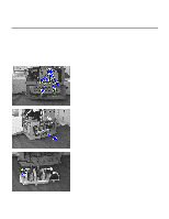
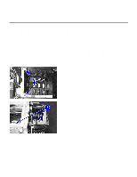
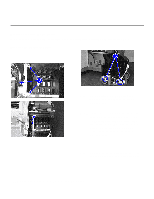
Replacement of Parts Installing the Power Supply Step 1. Slide in the new power supply. Step 2. Reconnect the power supply connector. Make sure the connector is secured properly. Step 3. Reinstall the power supply cover. Make sure the ESD clip is on the outside of the cover and the screw holes are aligned. Step 4. Replace the five screws. Do not over-tighten the plastic screws (the two at the bottom of the cover). Step 5. Replace the remaining components for the power supply (refer to Steps 3-14 of Installing the Power Knob from Replacement of Power Knob.) Removal and Replacement of Parts (without Calibration) 7-21
-
 1
1 -
2
-
3
-
4
-
5
-
6
-
7
-
8
-
9
-
10
-
11
-
12
-
13
-
14
-
15
-
16
-
17
-
18
-
19
-
20
-
21
-
22
-
23
-
24
-
25
-
26
-
27
-
28
-
29
-
30
-
31
-
32
-
33
-
34
-
35
-
36
-
37
-
38
-
39
-
40
-
41
-
42
-
43
-
44
-
45
-
46
-
47
-
48
-
49
-
50
-
51
-
52
-
53
-
54
-
55
-
56
-
57
-
58
-
59
-
60
-
61
-
62
-
63
-
64
-
65
-
66
-
67
-
68
-
69
-
70
-
71
-
72
-
73
-
74
-
75
-
76
-
77
-
78
-
79
-
80
-
81
-
82
-
83
-
84
-
85
-
86
-
87
-
88
-
89
-
90
-
91
-
92
-
93
-
94
-
95
-
96
-
97
-
98
-
99
-
100
-
101
-
102
-
103
-
104
-
105
-
106
-
107
-
108
-
109
-
110
-
111
-
112
-
113
-
114
-
115
-
116
-
117
-
118
-
119
-
120
-
121
-
122
-
123
-
124
-
125
-
126
-
127
-
128
-
129
-
130
-
131
-
132
-
133
-
134
-
135
-
136
-
137
-
138
-
139
-
140
-
141
-
142
-
143
-
144
-
145
-
146
-
147
-
148
-
149
-
150
-
151
-
152
-
153
-
154
-
155
-
156
-
157
-
158
-
159
-
160
-
161
-
162
-
163
-
164
-
165
-
 166
166 -
 167
167 -
 168
168 -
 169
169 -
 170
170 -
 171
171 -
 172
172 -
 173
173 -
 174
174 -
 175
175 -
 176
176 -
177
-
178
-
179
-
180
-
181
-
182
-
183
-
184
-
185
-
186
-
187
-
188
-
189
-
190
-
191
-
192
-
193
-
194
-
195
-
196
-
197
-
198
-
199
-
200
-
201
-
202
-
203
-
204
-
205
-
206
-
207
-
208
-
209
-
210
-
211
-
212
-
213
-
214
-
215
-
216
-
217
-
218
-
219
-
220
-
221
-
222
-
223
-
224
-
225
 |
 |

Removal and Replacement of Parts (without Calibration)
7-21
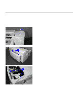
Replacement of Parts
Installing the Power Supply
Step 1.
Slide in the new power supply.
Step 2.
Reconnect the power supply connector.
Make sure the connector is secured properly.
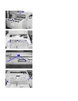
Step 3.
Reinstall the power supply cover.
Make sure the ESD clip is on the outside of the cover and the
screw holes are aligned.
Step 4.
Replace the five screws.
Do not over-tighten the plastic screws (the two at the bottom of the cover).
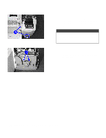
Step 5.
Replace the remaining components for the power supply (refer to
Steps 3-14
of
Installing the Power
Knob
from
Replacement of Power Knob.
)