HP 2500c Service Manual - Page 156
Installing the PCA
 |
View all HP 2500c manuals
Add to My Manuals
Save this manual to your list of manuals |
Page 156 highlights
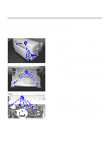
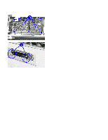
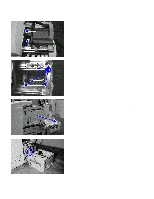
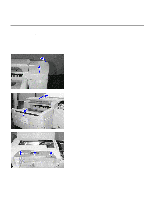
Replacement of Parts Installing the PCA Step 1. Attach the new PCA board, ensuring that the clips on the parallel port cable plug and the various connector cables do not cause any obstruction. Step 2. Replace the seven screws back to secure the PCA to the chassis. Step 3. Reattach the flex connectors carefully, gently pushing both ends of the black plastic fastener till they are seated firmly in the slots. Also reattach the power connector and the four connectors, ensuring that the black connectors are connected to the black slots, and the grey connectors to the grey slots respectively. Step 4. Place the metal PCA cover over the PCA card and ensure that the screw holes are aligned properly. Replace the four screws to fasten the cover plate to the rear access door. Step 5. If you have any peripheral accessory (e.g. MIO network card), reconnect it by sliding it in on the right side of the rear access door and tightening the two screws on the card to attach it firmly. Step 6. Close the rear access door. Plug in the power cord and turn on the printer. 7-6 Removal and Replacement of Parts (without Calibration)
-
 1
1 -
2
-
3
-
4
-
5
-
6
-
7
-
8
-
9
-
10
-
11
-
12
-
13
-
14
-
15
-
16
-
17
-
18
-
19
-
20
-
21
-
22
-
23
-
24
-
25
-
26
-
27
-
28
-
29
-
30
-
31
-
32
-
33
-
34
-
35
-
36
-
37
-
38
-
39
-
40
-
41
-
42
-
43
-
44
-
45
-
46
-
47
-
48
-
49
-
50
-
51
-
52
-
53
-
54
-
55
-
56
-
57
-
58
-
59
-
60
-
61
-
62
-
63
-
64
-
65
-
66
-
67
-
68
-
69
-
70
-
71
-
72
-
73
-
74
-
75
-
76
-
77
-
78
-
79
-
80
-
81
-
82
-
83
-
84
-
85
-
86
-
87
-
88
-
89
-
90
-
91
-
92
-
93
-
94
-
95
-
96
-
97
-
98
-
99
-
100
-
101
-
102
-
103
-
104
-
105
-
106
-
107
-
108
-
109
-
110
-
111
-
112
-
113
-
114
-
115
-
116
-
117
-
118
-
119
-
120
-
121
-
122
-
123
-
124
-
125
-
126
-
127
-
128
-
129
-
130
-
131
-
132
-
133
-
134
-
135
-
136
-
137
-
138
-
139
-
140
-
141
-
142
-
143
-
144
-
145
-
146
-
147
-
148
-
149
-
150
-
 151
151 -
 152
152 -
 153
153 -
 154
154 -
 155
155 -
 156
156 -
 157
157 -
 158
158 -
 159
159 -
 160
160 -
 161
161 -
162
-
163
-
164
-
165
-
166
-
167
-
168
-
169
-
170
-
171
-
172
-
173
-
174
-
175
-
176
-
177
-
178
-
179
-
180
-
181
-
182
-
183
-
184
-
185
-
186
-
187
-
188
-
189
-
190
-
191
-
192
-
193
-
194
-
195
-
196
-
197
-
198
-
199
-
200
-
201
-
202
-
203
-
204
-
205
-
206
-
207
-
208
-
209
-
210
-
211
-
212
-
213
-
214
-
215
-
216
-
217
-
218
-
219
-
220
-
221
-
222
-
223
-
224
-
225
 |
 |