HP 2500c Service Manual - Page 135
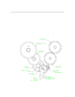
Fixed field sensors compare the amount of reflected light that is seen by two
 |
View all HP 2500c manuals
Add to My Manuals
Save this manual to your list of manuals |
Page 135 highlights
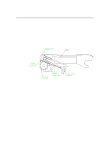
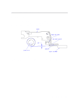
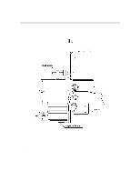
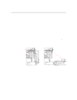
Paper Paths and Components Output stack sensing is based on fixed field proximity sensing using two LEDs side by side.These LEDs have both light source emitters as well as receivers. In short, it is based on the concept of fixed distance sensing and ignoring any objects that lie beyond their sensing range regardless of object surface reflectivity e.g. plain paper vs. glossy paper. (But Transparencies will affect the sensing distance, they are detected earlier by 8mm) Sensor is mounted on the carriage wall directly on top of the BOF of media (which is approx. 10mm). As BOF is the non-printed area, this is used as the reflecting surface for the light so that the variation in colour/text content of the output media does not have any influence. Fixed field sensors compare the amount of reflected light that is seen by two differently aimed receiver optical elements. A target is recognised as long as the amount of light reaching receiver seen by one receiver is greater than other. Distance of sensing( from the bottom of the sensor to paper full level) = 35mm Functional Overview 6-15
-
 1
1 -
2
-
3
-
4
-
5
-
6
-
7
-
8
-
9
-
10
-
11
-
12
-
13
-
14
-
15
-
16
-
17
-
18
-
19
-
20
-
21
-
22
-
23
-
24
-
25
-
26
-
27
-
28
-
29
-
30
-
31
-
32
-
33
-
34
-
35
-
36
-
37
-
38
-
39
-
40
-
41
-
42
-
43
-
44
-
45
-
46
-
47
-
48
-
49
-
50
-
51
-
52
-
53
-
54
-
55
-
56
-
57
-
58
-
59
-
60
-
61
-
62
-
63
-
64
-
65
-
66
-
67
-
68
-
69
-
70
-
71
-
72
-
73
-
74
-
75
-
76
-
77
-
78
-
79
-
80
-
81
-
82
-
83
-
84
-
85
-
86
-
87
-
88
-
89
-
90
-
91
-
92
-
93
-
94
-
95
-
96
-
97
-
98
-
99
-
100
-
101
-
102
-
103
-
104
-
105
-
106
-
107
-
108
-
109
-
110
-
111
-
112
-
113
-
114
-
115
-
116
-
117
-
118
-
119
-
120
-
121
-
122
-
123
-
124
-
125
-
126
-
127
-
128
-
129
-
 130
130 -
 131
131 -
 132
132 -
 133
133 -
 134
134 -
 135
135 -
 136
136 -
 137
137 -
 138
138 -
 139
139 -
 140
140 -
141
-
142
-
143
-
144
-
145
-
146
-
147
-
148
-
149
-
150
-
151
-
152
-
153
-
154
-
155
-
156
-
157
-
158
-
159
-
160
-
161
-
162
-
163
-
164
-
165
-
166
-
167
-
168
-
169
-
170
-
171
-
172
-
173
-
174
-
175
-
176
-
177
-
178
-
179
-
180
-
181
-
182
-
183
-
184
-
185
-
186
-
187
-
188
-
189
-
190
-
191
-
192
-
193
-
194
-
195
-
196
-
197
-
198
-
199
-
200
-
201
-
202
-
203
-
204
-
205
-
206
-
207
-
208
-
209
-
210
-
211
-
212
-
213
-
214
-
215
-
216
-
217
-
218
-
219
-
220
-
221
-
222
-
223
-
224
-
225
 |
 |