HP 2500c Service Manual - Page 130
Ramp Drive, Ramp slipping mechanism - movement
 |
View all HP 2500c manuals
Add to My Manuals
Save this manual to your list of manuals |
Page 130 highlights
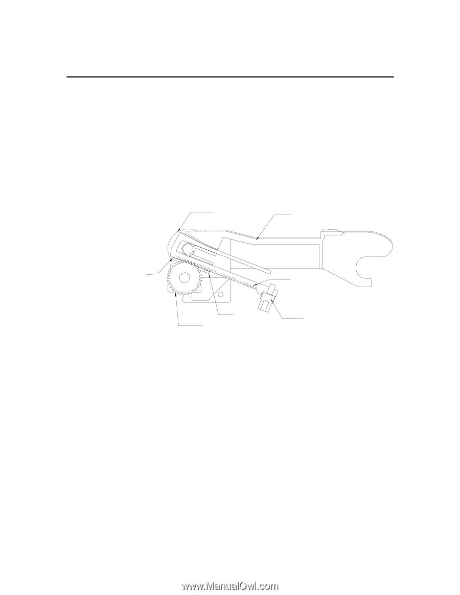
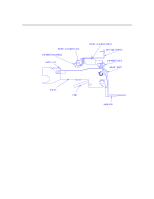
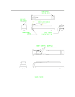
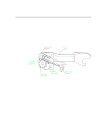
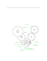
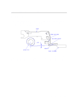
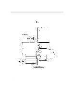
Paper Paths and Components Ramp Drive Ramps are driven by Stepper motor (Bi-polar) through gear train. Each ramp has rack tooth profile and individual pinion fitted in a shaft engages with rack tooth. The ramps can be moved in both directions (extended and withdrawn). Ramps are stopped in both directions mechanically by Platen surfaces. In the forward direction, ramps are stopped by stopper (snapped to it ) hitting the Platen surface. In the reverse direction, projection in the ramp hits the Platen surface. In reverse direction, projection in the ramp hits the Platen surface. Output roller Platen Stopper (on platen) Ramp Gear-ramp Stopper (on platen) Ramp stopper Ramp slipping mechanism Slipping arrangement is provided for the ramps. During Printer initialization as well as during resetting after Elec. Power disruption we need to bring the ramps back to their home position (withdrawn condition) as we will not know their current position. To achieve this ramps have to be overrun but at the same time the drive to the ramps should be cut-off once they have reached their home position. Axially loaded compression spring provides frictional force (400gm) to the slip-gear which transmits motion from the drive shaft to the ramp-gear. In case the resistance force from the ramps increases (due to stoppage) more than 400 gms,the spring compresses further and thereby slip-gear starts slipping. Force required to stall/ hold the ramp for slipping (measured on the face of the ramp i.e; opposite to the direction of ramp movement ) : 175-275 gm 6-10 Functional Overview
-
 1
1 -
2
-
3
-
4
-
5
-
6
-
7
-
8
-
9
-
10
-
11
-
12
-
13
-
14
-
15
-
16
-
17
-
18
-
19
-
20
-
21
-
22
-
23
-
24
-
25
-
26
-
27
-
28
-
29
-
30
-
31
-
32
-
33
-
34
-
35
-
36
-
37
-
38
-
39
-
40
-
41
-
42
-
43
-
44
-
45
-
46
-
47
-
48
-
49
-
50
-
51
-
52
-
53
-
54
-
55
-
56
-
57
-
58
-
59
-
60
-
61
-
62
-
63
-
64
-
65
-
66
-
67
-
68
-
69
-
70
-
71
-
72
-
73
-
74
-
75
-
76
-
77
-
78
-
79
-
80
-
81
-
82
-
83
-
84
-
85
-
86
-
87
-
88
-
89
-
90
-
91
-
92
-
93
-
94
-
95
-
96
-
97
-
98
-
99
-
100
-
101
-
102
-
103
-
104
-
105
-
106
-
107
-
108
-
109
-
110
-
111
-
112
-
113
-
114
-
115
-
116
-
117
-
118
-
119
-
120
-
121
-
122
-
123
-
124
-
 125
125 -
 126
126 -
 127
127 -
 128
128 -
 129
129 -
 130
130 -
 131
131 -
 132
132 -
 133
133 -
 134
134 -
 135
135 -
136
-
137
-
138
-
139
-
140
-
141
-
142
-
143
-
144
-
145
-
146
-
147
-
148
-
149
-
150
-
151
-
152
-
153
-
154
-
155
-
156
-
157
-
158
-
159
-
160
-
161
-
162
-
163
-
164
-
165
-
166
-
167
-
168
-
169
-
170
-
171
-
172
-
173
-
174
-
175
-
176
-
177
-
178
-
179
-
180
-
181
-
182
-
183
-
184
-
185
-
186
-
187
-
188
-
189
-
190
-
191
-
192
-
193
-
194
-
195
-
196
-
197
-
198
-
199
-
200
-
201
-
202
-
203
-
204
-
205
-
206
-
207
-
208
-
209
-
210
-
211
-
212
-
213
-
214
-
215
-
216
-
217
-
218
-
219
-
220
-
221
-
222
-
223
-
224
-
225
 |
 |