HP 2500c Service Manual - Page 158
service station.
 |
View all HP 2500c manuals
Add to My Manuals
Save this manual to your list of manuals |
Page 158 highlights
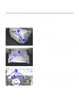
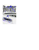
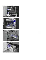
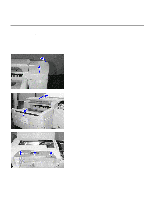
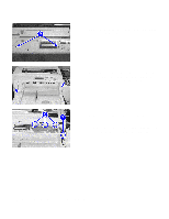
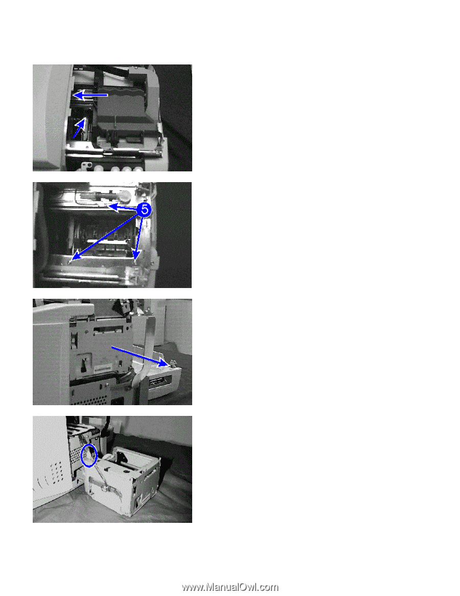
Step 4. Slide the ink carriage mechanism along the carriage rod to the left under the top cover. This will expose three screws, previously concealed under the ink carriage mechanism, that secure the service station. Step 5. Unscrew the three screws in the order shown on the chassis. Step 6. Remove the service station by sliding it out. Be careful of connecting cables when removing the service station. Step 7. Disconnect the service station connector. 7-8 Removal and Replacement of Parts (without Calibration)
-
 1
1 -
2
-
3
-
4
-
5
-
6
-
7
-
8
-
9
-
10
-
11
-
12
-
13
-
14
-
15
-
16
-
17
-
18
-
19
-
20
-
21
-
22
-
23
-
24
-
25
-
26
-
27
-
28
-
29
-
30
-
31
-
32
-
33
-
34
-
35
-
36
-
37
-
38
-
39
-
40
-
41
-
42
-
43
-
44
-
45
-
46
-
47
-
48
-
49
-
50
-
51
-
52
-
53
-
54
-
55
-
56
-
57
-
58
-
59
-
60
-
61
-
62
-
63
-
64
-
65
-
66
-
67
-
68
-
69
-
70
-
71
-
72
-
73
-
74
-
75
-
76
-
77
-
78
-
79
-
80
-
81
-
82
-
83
-
84
-
85
-
86
-
87
-
88
-
89
-
90
-
91
-
92
-
93
-
94
-
95
-
96
-
97
-
98
-
99
-
100
-
101
-
102
-
103
-
104
-
105
-
106
-
107
-
108
-
109
-
110
-
111
-
112
-
113
-
114
-
115
-
116
-
117
-
118
-
119
-
120
-
121
-
122
-
123
-
124
-
125
-
126
-
127
-
128
-
129
-
130
-
131
-
132
-
133
-
134
-
135
-
136
-
137
-
138
-
139
-
140
-
141
-
142
-
143
-
144
-
145
-
146
-
147
-
148
-
149
-
150
-
151
-
152
-
 153
153 -
 154
154 -
 155
155 -
 156
156 -
 157
157 -
 158
158 -
 159
159 -
 160
160 -
 161
161 -
 162
162 -
 163
163 -
164
-
165
-
166
-
167
-
168
-
169
-
170
-
171
-
172
-
173
-
174
-
175
-
176
-
177
-
178
-
179
-
180
-
181
-
182
-
183
-
184
-
185
-
186
-
187
-
188
-
189
-
190
-
191
-
192
-
193
-
194
-
195
-
196
-
197
-
198
-
199
-
200
-
201
-
202
-
203
-
204
-
205
-
206
-
207
-
208
-
209
-
210
-
211
-
212
-
213
-
214
-
215
-
216
-
217
-
218
-
219
-
220
-
221
-
222
-
223
-
224
-
225
 |
 |
Removal and Replacement of Parts (without Calibration)
7-8
Step 4.
Slide the ink carriage mechanism along the
carriage rod to the left under the top
cover. This will expose three screws,
previously concealed under the ink
carriage mechanism, that secure the
service station.
Step 5.
Unscrew the three screws in the order
shown on the chassis.
Step 6.
Remove the service station by sliding it
out.
Be careful of connecting cables when
removing the service station.
Step 7.
Disconnect the service station connector.