HP 2500c Service Manual - Page 173
Steps 3-14, Installing the Power Knob, Replacement of Power Knob.
 |
View all HP 2500c manuals
Add to My Manuals
Save this manual to your list of manuals |
Page 173 highlights
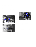
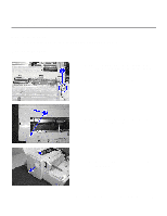
Replacement of Parts Installing the MIDS Step 1. Attach the retainer clip to the tubes and to fasten them in place to the chassis with the screw. Step 2. Fasten the screw between "C" and "M". Step 3. Replace the pump section, tilting it an angle such that the catch next to the yellow nozzle is latched first, and replace the screws. Step 4. Replace the remaining components for the MIDS (refer to Steps 3-14 of Installing the Power Knob from Replacement of Power Knob.) Removal and Replacement of Parts (without Calibration) 7-23
-
 1
1 -
2
-
3
-
4
-
5
-
6
-
7
-
8
-
9
-
10
-
11
-
12
-
13
-
14
-
15
-
16
-
17
-
18
-
19
-
20
-
21
-
22
-
23
-
24
-
25
-
26
-
27
-
28
-
29
-
30
-
31
-
32
-
33
-
34
-
35
-
36
-
37
-
38
-
39
-
40
-
41
-
42
-
43
-
44
-
45
-
46
-
47
-
48
-
49
-
50
-
51
-
52
-
53
-
54
-
55
-
56
-
57
-
58
-
59
-
60
-
61
-
62
-
63
-
64
-
65
-
66
-
67
-
68
-
69
-
70
-
71
-
72
-
73
-
74
-
75
-
76
-
77
-
78
-
79
-
80
-
81
-
82
-
83
-
84
-
85
-
86
-
87
-
88
-
89
-
90
-
91
-
92
-
93
-
94
-
95
-
96
-
97
-
98
-
99
-
100
-
101
-
102
-
103
-
104
-
105
-
106
-
107
-
108
-
109
-
110
-
111
-
112
-
113
-
114
-
115
-
116
-
117
-
118
-
119
-
120
-
121
-
122
-
123
-
124
-
125
-
126
-
127
-
128
-
129
-
130
-
131
-
132
-
133
-
134
-
135
-
136
-
137
-
138
-
139
-
140
-
141
-
142
-
143
-
144
-
145
-
146
-
147
-
148
-
149
-
150
-
151
-
152
-
153
-
154
-
155
-
156
-
157
-
158
-
159
-
160
-
161
-
162
-
163
-
164
-
165
-
166
-
167
-
 168
168 -
 169
169 -
 170
170 -
 171
171 -
 172
172 -
 173
173 -
 174
174 -
 175
175 -
 176
176 -
 177
177 -
 178
178 -
179
-
180
-
181
-
182
-
183
-
184
-
185
-
186
-
187
-
188
-
189
-
190
-
191
-
192
-
193
-
194
-
195
-
196
-
197
-
198
-
199
-
200
-
201
-
202
-
203
-
204
-
205
-
206
-
207
-
208
-
209
-
210
-
211
-
212
-
213
-
214
-
215
-
216
-
217
-
218
-
219
-
220
-
221
-
222
-
223
-
224
-
225
 |
 |

Removal and Replacement of Parts (without Calibration)
7-23
Replacement of Parts
Installing the MIDS
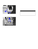
Step 1.
Attach the retainer clip to the tubes and
to fasten them in place to the chassis with the screw.
Step 2.
Fasten the screw between “C” and “M”.
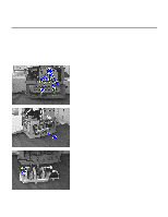
Step 3.
Replace the pump section, tilting it an angle such that the catch next to the yellow nozzle
is latched
first, and replace the screws.
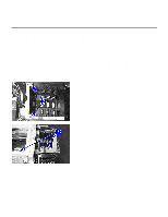
Step 4.
Replace the remaining components for the MIDS (refer to
Steps 3-14
of
Installing the Power Knob
from
Replacement of Power Knob.
)