HP 2500c Service Manual - Page 141
Dual Bin Pick And Feed Mechanism, Pick And Feed Schematic, E, The Dual Bin Pick And Feed
 |
View all HP 2500c manuals
Add to My Manuals
Save this manual to your list of manuals |
Page 141 highlights
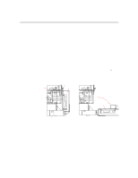
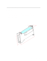
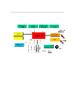
Paper Paths and Components Dual Bin Pick And Feed Mechanism Pick And Feed Schematic INPINCH ROLLER DRIVE ROLLER DIRECTION TROUGH 1 TROUGH 2 COF ~ 1.6 (BET ROLLER AND PAPER) GRAVITATIONAL FORCE PAPER PATH PICK ROLLER DIRECTION PICK FORCE SEPARATION SURFACE COF ~ 0.6 (BET SEP. PAD AND PAPER) Figure E The Dual Bin Pick And Feed The pick roller is mounted to a pivot arm such that when the paper tray is pushed into its position, the pick roller and the pivot arm will fall on the paper surface, as shown in Figure E. A DC motor is used to supply power to provide the pick force (µN, N=mg) to drive the top media sheet(s) against the separation surface in front of the tray. The angle of the separation surface with respect to the horizontal is in such that it ensures only one sheet of media is fed through. The media is fed continuously until it reaches the set of pinch rollers at the drive roller, before the drive roller takes over the driving force. Functional Overview 6-21
-
 1
1 -
2
-
3
-
4
-
5
-
6
-
7
-
8
-
9
-
10
-
11
-
12
-
13
-
14
-
15
-
16
-
17
-
18
-
19
-
20
-
21
-
22
-
23
-
24
-
25
-
26
-
27
-
28
-
29
-
30
-
31
-
32
-
33
-
34
-
35
-
36
-
37
-
38
-
39
-
40
-
41
-
42
-
43
-
44
-
45
-
46
-
47
-
48
-
49
-
50
-
51
-
52
-
53
-
54
-
55
-
56
-
57
-
58
-
59
-
60
-
61
-
62
-
63
-
64
-
65
-
66
-
67
-
68
-
69
-
70
-
71
-
72
-
73
-
74
-
75
-
76
-
77
-
78
-
79
-
80
-
81
-
82
-
83
-
84
-
85
-
86
-
87
-
88
-
89
-
90
-
91
-
92
-
93
-
94
-
95
-
96
-
97
-
98
-
99
-
100
-
101
-
102
-
103
-
104
-
105
-
106
-
107
-
108
-
109
-
110
-
111
-
112
-
113
-
114
-
115
-
116
-
117
-
118
-
119
-
120
-
121
-
122
-
123
-
124
-
125
-
126
-
127
-
128
-
129
-
130
-
131
-
132
-
133
-
134
-
135
-
 136
136 -
 137
137 -
 138
138 -
 139
139 -
 140
140 -
 141
141 -
 142
142 -
 143
143 -
 144
144 -
 145
145 -
 146
146 -
147
-
148
-
149
-
150
-
151
-
152
-
153
-
154
-
155
-
156
-
157
-
158
-
159
-
160
-
161
-
162
-
163
-
164
-
165
-
166
-
167
-
168
-
169
-
170
-
171
-
172
-
173
-
174
-
175
-
176
-
177
-
178
-
179
-
180
-
181
-
182
-
183
-
184
-
185
-
186
-
187
-
188
-
189
-
190
-
191
-
192
-
193
-
194
-
195
-
196
-
197
-
198
-
199
-
200
-
201
-
202
-
203
-
204
-
205
-
206
-
207
-
208
-
209
-
210
-
211
-
212
-
213
-
214
-
215
-
216
-
217
-
218
-
219
-
220
-
221
-
222
-
223
-
224
-
225
 |
 |
