IBM 621410U Hardware Maintenance Manual - Page 100
Tower model, Adapter fan, Power-off the computer and remove external cables.
 |
UPC - 087944665854
View all IBM 621410U manuals
Add to My Manuals
Save this manual to your list of manuals |
Page 100 highlights
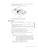
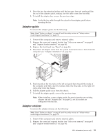
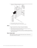
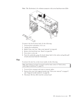
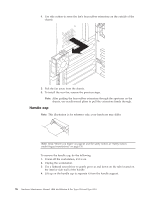
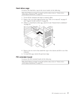
5. Disconnect all internal system board cables. Note: The drive cages and power supply have been removed in the illustration above for purposes of clarification. If these installed items impede your ability to easily access the system board, you can remove them from the computer (see "CD-ROM or diskette drive installation" on page 51 and "Power supply" on page 89). 6. Remove the seven screws that secure the system board to the chassis and lift the board up and out of the computer. Note: The system board for the desktop model has a tab on the bottom which fits into the notch on the floor of the chassis. 7. To install the system board, reverse the previous steps. Tower model The following section contains information on removing components of the tower model. Adapter fan Note: Not all tower model systems incorporate an adapter fan. To remove the adapter fan, do the following: Note: Read "Before you begin" on page 41 and the safety notices at "Safety notices (multi-lingual translations)" on page 135. 1. Power-off the computer and remove external cables. 2. Remove the cover and support bracket (see "Side cover removal" on page 63 and "Support bracket removal" on page 64). 3. Disconnect the fan cable from the system board. 92 Hardware Maintenance Manual: IBM IntelliStation E Pro Type 6204 and Type 6214
-
 1
1 -
2
-
3
-
4
-
5
-
6
-
7
-
8
-
9
-
10
-
11
-
12
-
13
-
14
-
15
-
16
-
17
-
18
-
19
-
20
-
21
-
22
-
23
-
24
-
25
-
26
-
27
-
28
-
29
-
30
-
31
-
32
-
33
-
34
-
35
-
36
-
37
-
38
-
39
-
40
-
41
-
42
-
43
-
44
-
45
-
46
-
47
-
48
-
49
-
50
-
51
-
52
-
53
-
54
-
55
-
56
-
57
-
58
-
59
-
60
-
61
-
62
-
63
-
64
-
65
-
66
-
67
-
68
-
69
-
70
-
71
-
72
-
73
-
74
-
75
-
76
-
77
-
78
-
79
-
80
-
81
-
82
-
83
-
84
-
85
-
86
-
87
-
88
-
89
-
90
-
91
-
92
-
93
-
94
-
 95
95 -
 96
96 -
 97
97 -
 98
98 -
 99
99 -
 100
100 -
 101
101 -
 102
102 -
 103
103 -
 104
104 -
 105
105 -
106
-
107
-
108
-
109
-
110
-
111
-
112
-
113
-
114
-
115
-
116
-
117
-
118
-
119
-
120
-
121
-
122
-
123
-
124
-
125
-
126
-
127
-
128
-
129
-
130
-
131
-
132
-
133
-
134
-
135
-
136
-
137
-
138
-
139
-
140
-
141
-
142
-
143
-
144
-
145
-
146
-
147
-
148
-
149
-
150
-
151
-
152
-
153
-
154
-
155
-
156
-
157
-
158
-
159
-
160
-
161
-
162
-
163
-
164
-
165
-
166
-
167
-
168
-
169
-
170
-
171
-
172
-
173
-
174
-
175
-
176
 |
 |
