IBM 621410U Hardware Maintenance Manual - Page 107
Power supply
 |
UPC - 087944665854
View all IBM 621410U manuals
Add to My Manuals
Save this manual to your list of manuals |
Page 107 highlights
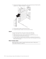
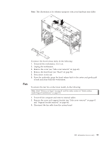
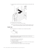
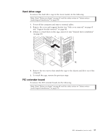
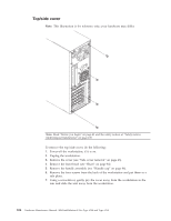
4. Disconnect the power/LED switch from the system board. 5. Disengage the lower tab of the power/LED switch by pressing upward on the lower tab of the power/LED switch until it comes loose. Note: It may be necessary to use the tip of a screwdriver to disengage the lower tab. 6. Push inward on the two tabs of the top section of the power/LED switch until it pops free of the chassis; then, remove it from the computer, making sure that the cable follows freely. 7. To install the power/LED switch, reverse the previous steps. Power supply To remove the power supply, do the following: Note: Read "Before you begin" on page 41 and the safety notices at "Safety notices (multi-lingual translations)" on page 135. 1. Power-off the computer and remove external cables. 2. Remove the cover and support bracket (see "Side cover removal" on page 63 and "Support bracket removal" on page 64). FRU information (service only) 99
-
 1
1 -
2
-
3
-
4
-
5
-
6
-
7
-
8
-
9
-
10
-
11
-
12
-
13
-
14
-
15
-
16
-
17
-
18
-
19
-
20
-
21
-
22
-
23
-
24
-
25
-
26
-
27
-
28
-
29
-
30
-
31
-
32
-
33
-
34
-
35
-
36
-
37
-
38
-
39
-
40
-
41
-
42
-
43
-
44
-
45
-
46
-
47
-
48
-
49
-
50
-
51
-
52
-
53
-
54
-
55
-
56
-
57
-
58
-
59
-
60
-
61
-
62
-
63
-
64
-
65
-
66
-
67
-
68
-
69
-
70
-
71
-
72
-
73
-
74
-
75
-
76
-
77
-
78
-
79
-
80
-
81
-
82
-
83
-
84
-
85
-
86
-
87
-
88
-
89
-
90
-
91
-
92
-
93
-
94
-
95
-
96
-
97
-
98
-
99
-
100
-
101
-
 102
102 -
 103
103 -
 104
104 -
 105
105 -
 106
106 -
 107
107 -
 108
108 -
 109
109 -
 110
110 -
 111
111 -
 112
112 -
113
-
114
-
115
-
116
-
117
-
118
-
119
-
120
-
121
-
122
-
123
-
124
-
125
-
126
-
127
-
128
-
129
-
130
-
131
-
132
-
133
-
134
-
135
-
136
-
137
-
138
-
139
-
140
-
141
-
142
-
143
-
144
-
145
-
146
-
147
-
148
-
149
-
150
-
151
-
152
-
153
-
154
-
155
-
156
-
157
-
158
-
159
-
160
-
161
-
162
-
163
-
164
-
165
-
166
-
167
-
168
-
169
-
170
-
171
-
172
-
173
-
174
-
175
-
176
 |
 |
