IBM 621410U Hardware Maintenance Manual - Page 80
Bay 5, 6 or 7 installation, located just above the front adapter-support bracket.
 |
UPC - 087944665854
View all IBM 621410U manuals
Add to My Manuals
Save this manual to your list of manuals |
Page 80 highlights
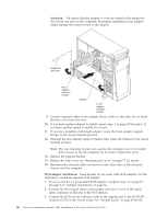
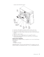
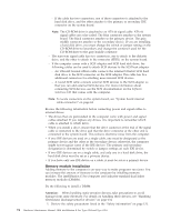
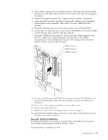
Note: You can install only a 3.5-in. device in bay 4. 11. If the drive is an IDE device, connect one end of the IDE signal cable into the back of the drive and the other end of the cable into the IDE connector on the system board. For the location of the IDE connectors, see "System board internal cable connectors" on page 44. If the drive is a SCSI device, connect one end of the SCSI signal cable into the back of the drive and the other end of the cable into the 68-pin connector on the SCSI adapter. Note: Route the signal cable so that it does not block the air flow to the rear of the drives or over the microprocessor. 12. Connect the power cable to the back of the drive. The connectors are keyed and can be inserted only one way. 13. If you have other options to install or remove, do so now. 14. Replace the support bracket. 15. Replace the side cover, see "Replacing the cover" on page 77 for details. 16. Reconnect the external cables and power cords; then turn on the attached devices and the computer. Bay 5, 6 or 7 installation: Bays 5, 6, and 7 are in the drive cage. The drive cage is located just above the front adapter-support bracket. Note: You might find it useful to work with the computer laying on its side. To install a drive in bay 5, 6, or 7, do the following: 1. Read the information in "Preinstallation steps" on page 70. 2. Turn off the computer and all attached devices. Disconnect all external cables and power cords; then remove the cover. See "Side cover removal" on page 63 for details. 72 Hardware Maintenance Manual: IBM IntelliStation E Pro Type 6204 and Type 6214
-
 1
1 -
2
-
3
-
4
-
5
-
6
-
7
-
8
-
9
-
10
-
11
-
12
-
13
-
14
-
15
-
16
-
17
-
18
-
19
-
20
-
21
-
22
-
23
-
24
-
25
-
26
-
27
-
28
-
29
-
30
-
31
-
32
-
33
-
34
-
35
-
36
-
37
-
38
-
39
-
40
-
41
-
42
-
43
-
44
-
45
-
46
-
47
-
48
-
49
-
50
-
51
-
52
-
53
-
54
-
55
-
56
-
57
-
58
-
59
-
60
-
61
-
62
-
63
-
64
-
65
-
66
-
67
-
68
-
69
-
70
-
71
-
72
-
73
-
74
-
 75
75 -
 76
76 -
 77
77 -
 78
78 -
 79
79 -
 80
80 -
 81
81 -
 82
82 -
 83
83 -
 84
84 -
 85
85 -
86
-
87
-
88
-
89
-
90
-
91
-
92
-
93
-
94
-
95
-
96
-
97
-
98
-
99
-
100
-
101
-
102
-
103
-
104
-
105
-
106
-
107
-
108
-
109
-
110
-
111
-
112
-
113
-
114
-
115
-
116
-
117
-
118
-
119
-
120
-
121
-
122
-
123
-
124
-
125
-
126
-
127
-
128
-
129
-
130
-
131
-
132
-
133
-
134
-
135
-
136
-
137
-
138
-
139
-
140
-
141
-
142
-
143
-
144
-
145
-
146
-
147
-
148
-
149
-
150
-
151
-
152
-
153
-
154
-
155
-
156
-
157
-
158
-
159
-
160
-
161
-
162
-
163
-
164
-
165
-
166
-
167
-
168
-
169
-
170
-
171
-
172
-
173
-
174
-
175
-
176
 |
 |
