IBM 621410U Hardware Maintenance Manual - Page 61
the drive cage., Slide the drive into the drive bay until the drive snaps into place, and replace
 |
UPC - 087944665854
View all IBM 621410U manuals
Add to My Manuals
Save this manual to your list of manuals |
Page 61 highlights
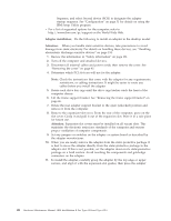
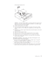
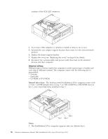
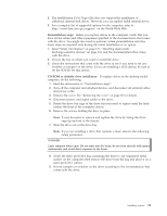
5. Remove the hard disk drive cage from the computer. 6. Slide the drive out of the drive bay. 7. Once the drive is free of the drive bay, remove the sliding rails and screws from this drive and carefully set them aside for installation on the replacement drive. 8. Touch the static-protective bag containing the drive to any unpainted metal surface on the compute, then remove the drive from the bag and place it on a static-protective surface. 9. Set any jumpers or switches on the drive according to the documentation that comes with the drive. 10. Attach the sliding rails, removed from the old drive in step 7, to the sides of the hard disk drive using screws that were set aside in step 7. 11. Slide the drive into the drive bay until the drive snaps into place, and replace the drive cage. 12. Connect one end of the IDE signal cable into the back of the drive and the other end of the cable into the IDE connector on the system board. For the location of the IDE connectors, see "System board internal cable connectors" on page 44. Installing options 53
-
 1
1 -
2
-
3
-
4
-
5
-
6
-
7
-
8
-
9
-
10
-
11
-
12
-
13
-
14
-
15
-
16
-
17
-
18
-
19
-
20
-
21
-
22
-
23
-
24
-
25
-
26
-
27
-
28
-
29
-
30
-
31
-
32
-
33
-
34
-
35
-
36
-
37
-
38
-
39
-
40
-
41
-
42
-
43
-
44
-
45
-
46
-
47
-
48
-
49
-
50
-
51
-
52
-
53
-
54
-
55
-
 56
56 -
 57
57 -
 58
58 -
 59
59 -
 60
60 -
 61
61 -
 62
62 -
 63
63 -
 64
64 -
 65
65 -
 66
66 -
67
-
68
-
69
-
70
-
71
-
72
-
73
-
74
-
75
-
76
-
77
-
78
-
79
-
80
-
81
-
82
-
83
-
84
-
85
-
86
-
87
-
88
-
89
-
90
-
91
-
92
-
93
-
94
-
95
-
96
-
97
-
98
-
99
-
100
-
101
-
102
-
103
-
104
-
105
-
106
-
107
-
108
-
109
-
110
-
111
-
112
-
113
-
114
-
115
-
116
-
117
-
118
-
119
-
120
-
121
-
122
-
123
-
124
-
125
-
126
-
127
-
128
-
129
-
130
-
131
-
132
-
133
-
134
-
135
-
136
-
137
-
138
-
139
-
140
-
141
-
142
-
143
-
144
-
145
-
146
-
147
-
148
-
149
-
150
-
151
-
152
-
153
-
154
-
155
-
156
-
157
-
158
-
159
-
160
-
161
-
162
-
163
-
164
-
165
-
166
-
167
-
168
-
169
-
170
-
171
-
172
-
173
-
174
-
175
-
176
 |
 |
