IBM 621410U Hardware Maintenance Manual - Page 87
Video connector, Signal, Signal description
 |
UPC - 087944665854
View all IBM 621410U manuals
Add to My Manuals
Save this manual to your list of manuals |
Page 87 highlights
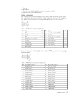
v Line out v Microphone v One video (optional multiple connectors on some models) v One Ultra160 SCSI (some models) Video connector The computer uses an AGP adapter located in the AGP slot on the system board. The video connector is on the adapter and is located on the rear of the computer. See "Input/output connectors" on page 78 for the location of this connector. 5 1 15 11 Table 8. Monitor connector-pin assignments Pin Signal I/O Pin Signal I/O 1 Red O 9 +5 V dc, used by DDC2B 2 Green I 10 Ground 3 Blue O 11 Monitor ID 0 - not used 4 Monitor ID 2 - not used I 12 DDC2B data I/O 5 Ground 13 Horizontal sync O 6 Red ground 14 Vertical sync O 7 Green ground 15 DDC2B clock I/O 8 Blue ground Some models come with a digital video interface (DVI) connector for connecting a digital monitor. 1 C1 C2 C3 C4 C5 Table 9. DVI monitor connector-pin assignments Pin Signal description Pin 1 TMDS Data2- 16 2 TMDS Data2+ 17 3 Data2/4 shield 18 4 TMDS Data4- 19 5 TMDS Data4+ 20 6 DDC clock 21 7 DDC Data 22 8 Analog VSync 23 9 PMDS Data1- 24 10 TMDS Data1+ C1 11 Data1/3 shield C2 12 TMDS Data3- C3 Signal description Hot plug detect TMDS Data0TMDS Data0+ Data0/5 shield TMDS Data5TMDS Data5+ Clock shield TMDS clock+ TMDS ClockAnalog red Analog green Analog blue Installing options 79
-
 1
1 -
2
-
3
-
4
-
5
-
6
-
7
-
8
-
9
-
10
-
11
-
12
-
13
-
14
-
15
-
16
-
17
-
18
-
19
-
20
-
21
-
22
-
23
-
24
-
25
-
26
-
27
-
28
-
29
-
30
-
31
-
32
-
33
-
34
-
35
-
36
-
37
-
38
-
39
-
40
-
41
-
42
-
43
-
44
-
45
-
46
-
47
-
48
-
49
-
50
-
51
-
52
-
53
-
54
-
55
-
56
-
57
-
58
-
59
-
60
-
61
-
62
-
63
-
64
-
65
-
66
-
67
-
68
-
69
-
70
-
71
-
72
-
73
-
74
-
75
-
76
-
77
-
78
-
79
-
80
-
81
-
 82
82 -
 83
83 -
 84
84 -
 85
85 -
 86
86 -
 87
87 -
 88
88 -
 89
89 -
 90
90 -
 91
91 -
 92
92 -
93
-
94
-
95
-
96
-
97
-
98
-
99
-
100
-
101
-
102
-
103
-
104
-
105
-
106
-
107
-
108
-
109
-
110
-
111
-
112
-
113
-
114
-
115
-
116
-
117
-
118
-
119
-
120
-
121
-
122
-
123
-
124
-
125
-
126
-
127
-
128
-
129
-
130
-
131
-
132
-
133
-
134
-
135
-
136
-
137
-
138
-
139
-
140
-
141
-
142
-
143
-
144
-
145
-
146
-
147
-
148
-
149
-
150
-
151
-
152
-
153
-
154
-
155
-
156
-
157
-
158
-
159
-
160
-
161
-
162
-
163
-
164
-
165
-
166
-
167
-
168
-
169
-
170
-
171
-
172
-
173
-
174
-
175
-
176
 |
 |
