IBM 621410U Hardware Maintenance Manual - Page 79
Bay 2 or 4 drive installation
 |
UPC - 087944665854
View all IBM 621410U manuals
Add to My Manuals
Save this manual to your list of manuals |
Page 79 highlights
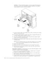
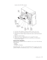
3. Check the instructions that come with the drive to see if you need to set any switches or jumpers on the drive. If you are installing a SCSI device, be sure to set the SCSI ID for that device. Bay 2 or 4 drive installation: Do the following to install a drive in bay 2 or 4: Attention: When handling static-sensitive devices, take precautions to avoid damage from static electricity. For details on handling these devices, see "Handling electrostatic discharge-sensitive devices" on page 134. 1. Read the information in "Preinstallation steps" on page 70. 2. Turn off the computer and attached devices and disconnect the external cables and power cords. 3. Remove the side cover. See "Side cover removal" on page 63 for details.) 4. Remove the support bracket. See "Support bracket removal" on page 64 for details. 5. Use a screwdriver to pry the filler panel and EMC shield away from the computer. Note: If you are installing a drive that contains a laser, observe the following safety precaution. DANGER Laser radiation when open. Do not stare into the beam. Do not view directly with optical instruments. Avoid direct exposure to the beam. 6. Touch the static-protective bag containing the drive to any unpainted metal surface on the computer; then remove the drive from the bag and place it on a static-protective surface. 7. Set any jumpers or switches on the drive according to the documentation that comes with the drive. 8. You might find it easier to install the new drive into the appropriate opening on the front, and then attach the cables. 9. If you are installing a 5.25-in. drive in bay 2, push the drive into the bay; then use the two screws to attach the drive to the drive cage. 10. If you are installing a 3.5-in. drive in bay 2, you must attach the 5.25-in conversion kit, supplied with the option, to the 3.5-in. drive. Installing options 71
-
 1
1 -
2
-
3
-
4
-
5
-
6
-
7
-
8
-
9
-
10
-
11
-
12
-
13
-
14
-
15
-
16
-
17
-
18
-
19
-
20
-
21
-
22
-
23
-
24
-
25
-
26
-
27
-
28
-
29
-
30
-
31
-
32
-
33
-
34
-
35
-
36
-
37
-
38
-
39
-
40
-
41
-
42
-
43
-
44
-
45
-
46
-
47
-
48
-
49
-
50
-
51
-
52
-
53
-
54
-
55
-
56
-
57
-
58
-
59
-
60
-
61
-
62
-
63
-
64
-
65
-
66
-
67
-
68
-
69
-
70
-
71
-
72
-
73
-
 74
74 -
 75
75 -
 76
76 -
 77
77 -
 78
78 -
 79
79 -
 80
80 -
 81
81 -
 82
82 -
 83
83 -
 84
84 -
85
-
86
-
87
-
88
-
89
-
90
-
91
-
92
-
93
-
94
-
95
-
96
-
97
-
98
-
99
-
100
-
101
-
102
-
103
-
104
-
105
-
106
-
107
-
108
-
109
-
110
-
111
-
112
-
113
-
114
-
115
-
116
-
117
-
118
-
119
-
120
-
121
-
122
-
123
-
124
-
125
-
126
-
127
-
128
-
129
-
130
-
131
-
132
-
133
-
134
-
135
-
136
-
137
-
138
-
139
-
140
-
141
-
142
-
143
-
144
-
145
-
146
-
147
-
148
-
149
-
150
-
151
-
152
-
153
-
154
-
155
-
156
-
157
-
158
-
159
-
160
-
161
-
162
-
163
-
164
-
165
-
166
-
167
-
168
-
169
-
170
-
171
-
172
-
173
-
174
-
175
-
176
 |
 |
