IBM 621410U Hardware Maintenance Manual - Page 81
Power and signal cables for internal drives
 |
UPC - 087944665854
View all IBM 621410U manuals
Add to My Manuals
Save this manual to your list of manuals |
Page 81 highlights
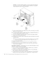
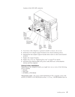
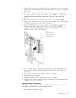
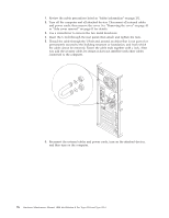
3. Remove the support bracket. 4. If the computer has hard disk drives preinstalled in the drive cage, disconnect the power and signal cables from the rear of the drives. 5. Grasp the drive cage and rotate the cage out (middle view) of the computer until it locks into place with the drive-cage retention tab. The open ends of the drive slots and installed drives will face you. Note: Ensure that the drive cage locks into place over the drive-cage retention tab by pressing the drive cage all the way up. 6. Attach the guide rails to the side of the drive using the screws and blue rails provided in the drive cage. 7. Slide the drive into the drive cage until the plastic tabs on the drive guide rails lock into place in the drive cage. Note: Clear any cables that might impede the replacement of the drive cage. 8. Lift the drive cage up, and press in on the drive-'cage release tab; then rotate the cage back into the computer (right view). 9. Connect the power and signal cables to the rear of each drive. Note: Route the signal cable so that it does not block the air flow to the rear of the drives or over the microprocessor. 10. If you have other options to install or remove, do so now. 11. Replace the support bracket. 12. Replace the side cover, see "Replacing the cover" on page 77 for details. 13. Reconnect the external cables and power cords; then turn on the attached devices and the computer. Power and signal cables for internal drives: The computer uses cables to connect IDE and SCSI devices to the power supply and to the system board. The following cables are provided: v Four-wire power cables connect the drives to the power supply. At the end of these cables are plastic connectors that attach to different drives; these connectors vary in size. Also, certain power cables attach to the system board. v Flat signal cables, also called ribbon cables, connect IDE, SCSI, and diskette drives to the system board. Two or three sizes of ribbon cables come with the computer. - The wider IDE signal cable has two or three connectors. - If the cable has three connectors, one of these connectors is attached to the drive, one is a spare, and the third attaches to the primary or secondary IDE connector on the system board. Installing options 73
-
 1
1 -
2
-
3
-
4
-
5
-
6
-
7
-
8
-
9
-
10
-
11
-
12
-
13
-
14
-
15
-
16
-
17
-
18
-
19
-
20
-
21
-
22
-
23
-
24
-
25
-
26
-
27
-
28
-
29
-
30
-
31
-
32
-
33
-
34
-
35
-
36
-
37
-
38
-
39
-
40
-
41
-
42
-
43
-
44
-
45
-
46
-
47
-
48
-
49
-
50
-
51
-
52
-
53
-
54
-
55
-
56
-
57
-
58
-
59
-
60
-
61
-
62
-
63
-
64
-
65
-
66
-
67
-
68
-
69
-
70
-
71
-
72
-
73
-
74
-
75
-
 76
76 -
 77
77 -
 78
78 -
 79
79 -
 80
80 -
 81
81 -
 82
82 -
 83
83 -
 84
84 -
 85
85 -
 86
86 -
87
-
88
-
89
-
90
-
91
-
92
-
93
-
94
-
95
-
96
-
97
-
98
-
99
-
100
-
101
-
102
-
103
-
104
-
105
-
106
-
107
-
108
-
109
-
110
-
111
-
112
-
113
-
114
-
115
-
116
-
117
-
118
-
119
-
120
-
121
-
122
-
123
-
124
-
125
-
126
-
127
-
128
-
129
-
130
-
131
-
132
-
133
-
134
-
135
-
136
-
137
-
138
-
139
-
140
-
141
-
142
-
143
-
144
-
145
-
146
-
147
-
148
-
149
-
150
-
151
-
152
-
153
-
154
-
155
-
156
-
157
-
158
-
159
-
160
-
161
-
162
-
163
-
164
-
165
-
166
-
167
-
168
-
169
-
170
-
171
-
172
-
173
-
174
-
175
-
176
 |
 |
