IBM 621410U Hardware Maintenance Manual - Page 98
Speaker, Important
 |
UPC - 087944665854
View all IBM 621410U manuals
Add to My Manuals
Save this manual to your list of manuals |
Page 98 highlights
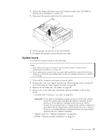
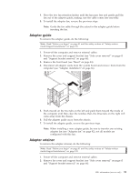
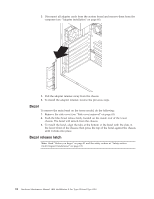
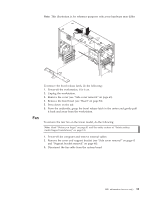
a. Detach the fan sink cable. b. Loosen the two captive screws on either side (in leaf spring enclosures) of the fansink. c. With the two captive screws loosened, pivot the leaf spring assemblies outward and out of the notches on the fansink assembly. d. Lift the fan sink up and out of the computer. Note: It may be necessary to gently twist the fansink to loosen it from the processor. Important: Be careful when handling the adhesive material on the processor. If the adhesive material on the processor will be reused, do not contaminate it. If replacement adhesive material is provided with the replacement part, be sure to remove all traces of existing adhesive material from the processor before applying the new adhesive material. 7. Free the processor from the system board by rotating the processor socket lever arm upward to its maximum vertical position. 8. Lift the processor up and out of the computer. 9. To install a processor, reverse the previous steps. Note: When reconnecting the fansink cable to the system board, be sure to connect the cable to the connector marked ″CPU fan″. Speaker To remove the speaker, do the following: Note: Read "Before you begin" on page 41 and the safety notices at "Safety notices (multi-lingual translations)" on page 135. 1. Power-off the computer and remove external cables. 2. Remove the cover and support bracket (see "Removing the cover" on page 45 and "Removing the frame support bracket" on page 46). 90 Hardware Maintenance Manual: IBM IntelliStation E Pro Type 6204 and Type 6214
-
 1
1 -
2
-
3
-
4
-
5
-
6
-
7
-
8
-
9
-
10
-
11
-
12
-
13
-
14
-
15
-
16
-
17
-
18
-
19
-
20
-
21
-
22
-
23
-
24
-
25
-
26
-
27
-
28
-
29
-
30
-
31
-
32
-
33
-
34
-
35
-
36
-
37
-
38
-
39
-
40
-
41
-
42
-
43
-
44
-
45
-
46
-
47
-
48
-
49
-
50
-
51
-
52
-
53
-
54
-
55
-
56
-
57
-
58
-
59
-
60
-
61
-
62
-
63
-
64
-
65
-
66
-
67
-
68
-
69
-
70
-
71
-
72
-
73
-
74
-
75
-
76
-
77
-
78
-
79
-
80
-
81
-
82
-
83
-
84
-
85
-
86
-
87
-
88
-
89
-
90
-
91
-
92
-
 93
93 -
 94
94 -
 95
95 -
 96
96 -
 97
97 -
 98
98 -
 99
99 -
 100
100 -
 101
101 -
 102
102 -
 103
103 -
104
-
105
-
106
-
107
-
108
-
109
-
110
-
111
-
112
-
113
-
114
-
115
-
116
-
117
-
118
-
119
-
120
-
121
-
122
-
123
-
124
-
125
-
126
-
127
-
128
-
129
-
130
-
131
-
132
-
133
-
134
-
135
-
136
-
137
-
138
-
139
-
140
-
141
-
142
-
143
-
144
-
145
-
146
-
147
-
148
-
149
-
150
-
151
-
152
-
153
-
154
-
155
-
156
-
157
-
158
-
159
-
160
-
161
-
162
-
163
-
164
-
165
-
166
-
167
-
168
-
169
-
170
-
171
-
172
-
173
-
174
-
175
-
176
 |
 |
