IBM 621410U Hardware Maintenance Manual - Page 97
Power supply, Processor / fan sink, Swing the CD-ROM drive cage up see
 |
UPC - 087944665854
View all IBM 621410U manuals
Add to My Manuals
Save this manual to your list of manuals |
Page 97 highlights
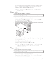
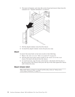
6. To install the power/LED switch, reverse the previous steps. Power supply To remove the power supply, do the following: Note: Read "Before you begin" on page 41 and the safety notices at "Safety notices (multi-lingual translations)" on page 135. 1. Power-off the computer and remove external cables. 2. Remove the cover and support bracket (see "Removing the cover" on page 45 and "Removing the frame support bracket" on page 46). 3. Swing the floppy disk drive cage up. 4. Disconnect the internal power supply cables. 5. Remove the two screws that secure the power supply to the chassis. 6. Lift the power supply out of the chassis. 7. To replace the power supply, reverse the previous steps. Processor / fan sink To remove the processor and fan sink, do the following: Note: Read "Before you begin" on page 41 and the safety notices at "Safety notices (multi-lingual translations)" on page 135. 1. Power-off the computer and remove external cables. 2. Remove the cover and support bracket (see "Removing the cover" on page 45 and "Removing the frame support bracket" on page 46). 3. Remove the air baffle (see "Air baffle" on page 87). 4. Swing the CD-ROM drive cage up (see "CD-ROM or diskette drive installation" on page 51). 5. Disconnect any cables that impede access to the processor. 6. Remove fan sink from processor: Note: The fansink and underlying heatsink are attached and do not need to be separated from each other. Remove the fansink/heatsink assembly from the processor as a single unit. FRU information (service only) 89
-
 1
1 -
2
-
3
-
4
-
5
-
6
-
7
-
8
-
9
-
10
-
11
-
12
-
13
-
14
-
15
-
16
-
17
-
18
-
19
-
20
-
21
-
22
-
23
-
24
-
25
-
26
-
27
-
28
-
29
-
30
-
31
-
32
-
33
-
34
-
35
-
36
-
37
-
38
-
39
-
40
-
41
-
42
-
43
-
44
-
45
-
46
-
47
-
48
-
49
-
50
-
51
-
52
-
53
-
54
-
55
-
56
-
57
-
58
-
59
-
60
-
61
-
62
-
63
-
64
-
65
-
66
-
67
-
68
-
69
-
70
-
71
-
72
-
73
-
74
-
75
-
76
-
77
-
78
-
79
-
80
-
81
-
82
-
83
-
84
-
85
-
86
-
87
-
88
-
89
-
90
-
91
-
 92
92 -
 93
93 -
 94
94 -
 95
95 -
 96
96 -
 97
97 -
 98
98 -
 99
99 -
 100
100 -
 101
101 -
 102
102 -
103
-
104
-
105
-
106
-
107
-
108
-
109
-
110
-
111
-
112
-
113
-
114
-
115
-
116
-
117
-
118
-
119
-
120
-
121
-
122
-
123
-
124
-
125
-
126
-
127
-
128
-
129
-
130
-
131
-
132
-
133
-
134
-
135
-
136
-
137
-
138
-
139
-
140
-
141
-
142
-
143
-
144
-
145
-
146
-
147
-
148
-
149
-
150
-
151
-
152
-
153
-
154
-
155
-
156
-
157
-
158
-
159
-
160
-
161
-
162
-
163
-
164
-
165
-
166
-
167
-
168
-
169
-
170
-
171
-
172
-
173
-
174
-
175
-
176
 |
 |
