IBM 621410U Hardware Maintenance Manual - Page 65
Tower model, The following illustration shows the locations of major components in the tower
 |
UPC - 087944665854
View all IBM 621410U manuals
Add to My Manuals
Save this manual to your list of manuals |
Page 65 highlights
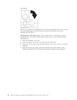
cover release latch to lock the cover. 3. Reconnect the external cables and power cords to the computer; then connect the power cords to electrical outlets. 4. Turn on the attached devices; then turn on the computer. Tower model The following illustration shows the locations of major components in the tower model computer. Rear adapter retention bracket Memory modules Microprocessor EMC shield Filler panel System board Drive cage Front adapter retention bracket Support bracket Cover Keylock button Front door Installing options 57
-
 1
1 -
2
-
3
-
4
-
5
-
6
-
7
-
8
-
9
-
10
-
11
-
12
-
13
-
14
-
15
-
16
-
17
-
18
-
19
-
20
-
21
-
22
-
23
-
24
-
25
-
26
-
27
-
28
-
29
-
30
-
31
-
32
-
33
-
34
-
35
-
36
-
37
-
38
-
39
-
40
-
41
-
42
-
43
-
44
-
45
-
46
-
47
-
48
-
49
-
50
-
51
-
52
-
53
-
54
-
55
-
56
-
57
-
58
-
59
-
 60
60 -
 61
61 -
 62
62 -
 63
63 -
 64
64 -
 65
65 -
 66
66 -
 67
67 -
 68
68 -
 69
69 -
 70
70 -
71
-
72
-
73
-
74
-
75
-
76
-
77
-
78
-
79
-
80
-
81
-
82
-
83
-
84
-
85
-
86
-
87
-
88
-
89
-
90
-
91
-
92
-
93
-
94
-
95
-
96
-
97
-
98
-
99
-
100
-
101
-
102
-
103
-
104
-
105
-
106
-
107
-
108
-
109
-
110
-
111
-
112
-
113
-
114
-
115
-
116
-
117
-
118
-
119
-
120
-
121
-
122
-
123
-
124
-
125
-
126
-
127
-
128
-
129
-
130
-
131
-
132
-
133
-
134
-
135
-
136
-
137
-
138
-
139
-
140
-
141
-
142
-
143
-
144
-
145
-
146
-
147
-
148
-
149
-
150
-
151
-
152
-
153
-
154
-
155
-
156
-
157
-
158
-
159
-
160
-
161
-
162
-
163
-
164
-
165
-
166
-
167
-
168
-
169
-
170
-
171
-
172
-
173
-
174
-
175
-
176
 |
 |

cover release latch to lock the cover.
3.
Reconnect the external cables and power cords to the computer; then connect
the power cords to electrical outlets.
4.
Turn on the attached devices; then turn on the computer.
Tower model
The following illustration shows the locations of major components in the tower
model computer.
Rear adapter
retention bracket
Front adapter
retention bracket
Drive cage
Microprocessor
Memory modules
System board
Cover
Support bracket
EMC
shield
Filler
panel
Front door
Keylock button
Installing options
57