IBM 621410U Hardware Maintenance Manual - Page 82
Memory module installation, designation is determined by switch or jumper settings on each IDE device.
 |
UPC - 087944665854
View all IBM 621410U manuals
Add to My Manuals
Save this manual to your list of manuals |
Page 82 highlights
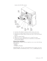
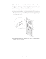
- If the cable has two connectors, one of these connectors is attached to the hard disk drive, and the other attaches to the primary or secondary IDE connector on the system board. Note: The CD-ROM drive is attached to an ATA 66 signal cable. ATA 66 signal cables are color-coded. The blue connector attaches to the system board. The black connector attaches to the primary device. The gray middle connector attaches to the secondary device. If you are installing a hard disk drive, you must change the switch or jumper setting on the CD-ROM drive to secondary and change the connector used for the CD-ROM drive to the gray middle connector. - The narrower signal cable has two connectors, one to attach to the diskette drive, and the other to attach to the connector (FDD1) on the system board. - If the computer comes with a SCSI adapter and SCSI hard disk drive, the following cables can be used to attach SCSI devices to the SCSI host adapter: - An Ultra160 twisted ribbon cable connects the internal Ultra160 SCSI hard disk drive to the SCSI connector on the SCSI adapter. This cable has five additional connectors for attaching more internal SCSI devices. - A round SCSI cable connects external SCSI devices to the SCSI adapter so that you can add external SCSI devices. For more information about connecting SCSI devices, see the SCSI documentation on the Software Selections CD that comes with the computer. Note: To locate connectors on the system board, see "System board internal cable connectors" on page 44. Review the following information before connecting power and signal cables to internal drives: v The drives that are preinstalled in the computer come with power and signal cables attached. If you replace any drives, it is important to remember which cable is attached to which drive. v When you install a drive, ensure that the drive connector at the end of the signal cable is connected to the drive and that the drive connector at the other end is connected to the system board. This reduces electronic noise from the computer. v If two IDE devices are used on a single cable, one must be designated as the primary device and the other as the secondary device; otherwise, the computer might not recognize some of the IDE devices. The primary and secondary designation is determined by switch or jumper settings on each IDE device. v If two IDE devices are on a single cable, and only one is a hard disk drive, the hard disk drive must be set as a primary device. v If you have only one IDE device on a cable, it must be set as a primary device. Memory module installation Adding memory to the computer is an easy way to make programs run faster. You can increase the amount of memory in the computer by installing memory modules. The IntelliStation E Pro computer uses industry-standard dual inline memory modules (DIMMs). Do the following to install a DIMM: Attention: When handling static-sensitive devices, take precautions to avoid damage from static electricity. For details on handling these devices, see "Handling electrostatic discharge-sensitive devices" on page 134. 1. Review the safety precautions listed in the "Safety information" on page 131. 74 Hardware Maintenance Manual: IBM IntelliStation E Pro Type 6204 and Type 6214
-
 1
1 -
2
-
3
-
4
-
5
-
6
-
7
-
8
-
9
-
10
-
11
-
12
-
13
-
14
-
15
-
16
-
17
-
18
-
19
-
20
-
21
-
22
-
23
-
24
-
25
-
26
-
27
-
28
-
29
-
30
-
31
-
32
-
33
-
34
-
35
-
36
-
37
-
38
-
39
-
40
-
41
-
42
-
43
-
44
-
45
-
46
-
47
-
48
-
49
-
50
-
51
-
52
-
53
-
54
-
55
-
56
-
57
-
58
-
59
-
60
-
61
-
62
-
63
-
64
-
65
-
66
-
67
-
68
-
69
-
70
-
71
-
72
-
73
-
74
-
75
-
76
-
 77
77 -
 78
78 -
 79
79 -
 80
80 -
 81
81 -
 82
82 -
 83
83 -
 84
84 -
 85
85 -
 86
86 -
 87
87 -
88
-
89
-
90
-
91
-
92
-
93
-
94
-
95
-
96
-
97
-
98
-
99
-
100
-
101
-
102
-
103
-
104
-
105
-
106
-
107
-
108
-
109
-
110
-
111
-
112
-
113
-
114
-
115
-
116
-
117
-
118
-
119
-
120
-
121
-
122
-
123
-
124
-
125
-
126
-
127
-
128
-
129
-
130
-
131
-
132
-
133
-
134
-
135
-
136
-
137
-
138
-
139
-
140
-
141
-
142
-
143
-
144
-
145
-
146
-
147
-
148
-
149
-
150
-
151
-
152
-
153
-
154
-
155
-
156
-
157
-
158
-
159
-
160
-
161
-
162
-
163
-
164
-
165
-
166
-
167
-
168
-
169
-
170
-
171
-
172
-
173
-
174
-
175
-
176
 |
 |
