IBM 621410U Hardware Maintenance Manual - Page 90
Serial connectors, Ethernet connector, Universal Serial Bus connectors, Important, Notes
 |
UPC - 087944665854
View all IBM 621410U manuals
Add to My Manuals
Save this manual to your list of manuals |
Page 90 highlights
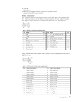
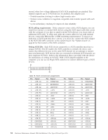
Serial connectors The computer has two standard 9-pin D-shell serial connectors: Serial connector 1 and Serial connector 2. See "Input/output connectors" on page 78 for their location. 1 5 6 9 Table 13. Serial-port connectors pin-number assignments Pin Signal Pin Signal 1 Data carrier detect 6 Data set ready 2 Receive data 7 Request to send 3 Transmit data 8 Clear to send 4 Data terminal ready 9 Ring indicator 5 Signal ground Ethernet connector The computer comes with an integrated Ethernet controller. This controller provides an interface for connecting to 10-Mbps or 100-Mbps networks and provides full-duplex capability, which enables simultaneous transmission and reception of data on an Ethernet local area network (LAN). To access the Ethernet connector, attach a Category 3, 4, or 5 unshielded twisted-pair (UTP) cable to the RJ-45 connector on the rear of the computer, see "Input/output connectors" on page 78. Important: To operate the computer within FCC Class A or Class B limits, use a category 5 Ethernet cable. Table 14. Ethernet RJ-45 connector pin-number assignments Pin Signal Pin Signal 1 Transmit data+ 5 Not connected 2 Transmit 6 Receive data - 3 Receive data+ 7 Not connected 4 Not connected 8 Not connected Universal Serial Bus connectors The computer has two Universal Serial Bus (USB) connectors for optional telephony and multimedia devices. USB devices configure automatically with Plug and Play technology. Notes: 1. If you attach a standard (non-USB) keyboard to the keyboard connector, the USB connectors and devices will be disabled during the power-on self-test. 82 Hardware Maintenance Manual: IBM IntelliStation E Pro Type 6204 and Type 6214
-
 1
1 -
2
-
3
-
4
-
5
-
6
-
7
-
8
-
9
-
10
-
11
-
12
-
13
-
14
-
15
-
16
-
17
-
18
-
19
-
20
-
21
-
22
-
23
-
24
-
25
-
26
-
27
-
28
-
29
-
30
-
31
-
32
-
33
-
34
-
35
-
36
-
37
-
38
-
39
-
40
-
41
-
42
-
43
-
44
-
45
-
46
-
47
-
48
-
49
-
50
-
51
-
52
-
53
-
54
-
55
-
56
-
57
-
58
-
59
-
60
-
61
-
62
-
63
-
64
-
65
-
66
-
67
-
68
-
69
-
70
-
71
-
72
-
73
-
74
-
75
-
76
-
77
-
78
-
79
-
80
-
81
-
82
-
83
-
84
-
 85
85 -
 86
86 -
 87
87 -
 88
88 -
 89
89 -
 90
90 -
 91
91 -
 92
92 -
 93
93 -
 94
94 -
 95
95 -
96
-
97
-
98
-
99
-
100
-
101
-
102
-
103
-
104
-
105
-
106
-
107
-
108
-
109
-
110
-
111
-
112
-
113
-
114
-
115
-
116
-
117
-
118
-
119
-
120
-
121
-
122
-
123
-
124
-
125
-
126
-
127
-
128
-
129
-
130
-
131
-
132
-
133
-
134
-
135
-
136
-
137
-
138
-
139
-
140
-
141
-
142
-
143
-
144
-
145
-
146
-
147
-
148
-
149
-
150
-
151
-
152
-
153
-
154
-
155
-
156
-
157
-
158
-
159
-
160
-
161
-
162
-
163
-
164
-
165
-
166
-
167
-
168
-
169
-
170
-
171
-
172
-
173
-
174
-
175
-
176
 |
 |
