IBM 621410U Hardware Maintenance Manual - Page 89
Parallel connector, Viewing or changing the connector assignments, Parallel connector pin-assignments
 |
UPC - 087944665854
View all IBM 621410U manuals
Add to My Manuals
Save this manual to your list of manuals |
Page 89 highlights
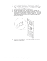
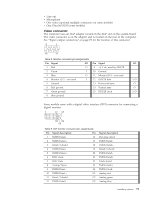
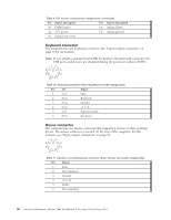
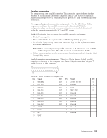
Parallel connector The computer has one parallel connector. This connector supports three standard Institute of Electrical and Electronics Engineers (IEEE) 1284 modes of operation: standard parallel port (SPP), enhanced parallel port (EPP), and extended capability port (ECP). Viewing or changing the connector assignments: Use the IBM Setup Utility program to configure the parallel connector as bi-directional. With this configuration, data can be read from and written to a device. In bidirectional mode, the computer supports the ECP and EPP modes. Do the following to view or change the parallel-connector assignment: 1. Restart the computer. 2. Press and hold the F1 key to launch the IBM Setup Utility program. 3. On the IBM Setup Utility menu, use the cursor keys on the keyboard to select Devices"Parallel Port. Note: When you configure the parallel connector as bi-directional, use an IEEE 1284-compliant cable. The cable must not exceed 3 meters (9.8 ft.). 4. Follow the instructions on the screen to save the changes and exit from the IBM Setup Utility menu. Parallel connector pin-assignments: There is a 25-pin, female D-shell parallel connector on the rear of the computer, see "Input/output connectors" on page 78 for the location of this connector. 13 1 25 14 Table 12. Parallel connector-pin assignments Pin Signal I/O Pin Signal I/O 1 STROBE# I/O 14 AUTO FD XT# O 2 Data bit 0 I/O 15 ERROR# I 3 Data bit 1 I/O 16 INIT# O 4 Data bit 2 I/O 17 SLCT IN# O 5 Data bit 3 I/O 18 Ground 6 Data bit 4 I/O 19 Ground 7 Data bit 5 I/O 20 Ground 8 Data bit 6 I/O 21 Ground 9 Data bit 7 I/O 22 Ground 10 ACK# I 23 Ground 11 BUSY I 24 Ground 12 PE I 25 Ground 13 SLCT I Installing options 81
-
 1
1 -
2
-
3
-
4
-
5
-
6
-
7
-
8
-
9
-
10
-
11
-
12
-
13
-
14
-
15
-
16
-
17
-
18
-
19
-
20
-
21
-
22
-
23
-
24
-
25
-
26
-
27
-
28
-
29
-
30
-
31
-
32
-
33
-
34
-
35
-
36
-
37
-
38
-
39
-
40
-
41
-
42
-
43
-
44
-
45
-
46
-
47
-
48
-
49
-
50
-
51
-
52
-
53
-
54
-
55
-
56
-
57
-
58
-
59
-
60
-
61
-
62
-
63
-
64
-
65
-
66
-
67
-
68
-
69
-
70
-
71
-
72
-
73
-
74
-
75
-
76
-
77
-
78
-
79
-
80
-
81
-
82
-
83
-
 84
84 -
 85
85 -
 86
86 -
 87
87 -
 88
88 -
 89
89 -
 90
90 -
 91
91 -
 92
92 -
 93
93 -
 94
94 -
95
-
96
-
97
-
98
-
99
-
100
-
101
-
102
-
103
-
104
-
105
-
106
-
107
-
108
-
109
-
110
-
111
-
112
-
113
-
114
-
115
-
116
-
117
-
118
-
119
-
120
-
121
-
122
-
123
-
124
-
125
-
126
-
127
-
128
-
129
-
130
-
131
-
132
-
133
-
134
-
135
-
136
-
137
-
138
-
139
-
140
-
141
-
142
-
143
-
144
-
145
-
146
-
147
-
148
-
149
-
150
-
151
-
152
-
153
-
154
-
155
-
156
-
157
-
158
-
159
-
160
-
161
-
162
-
163
-
164
-
165
-
166
-
167
-
168
-
169
-
170
-
171
-
172
-
173
-
174
-
175
-
176
 |
 |
