IBM 621410U Hardware Maintenance Manual - Page 62
Power and signal cables for internal drives, The narrower signal cable has two connectors
 |
UPC - 087944665854
View all IBM 621410U manuals
Add to My Manuals
Save this manual to your list of manuals |
Page 62 highlights
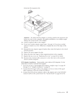
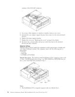
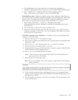
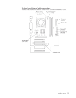
Note: Make sure to route the signal cable so that it does not block the air flow to the rear of the drives or over the microprocessor. 13. Connect a power cable to the back of the drive. The connectors are keyed and can be inserted only one way. 14. If you have other options to install or remove, do so now. 15. Replace the cover. See "Replacing the cover" on page 56 for details. 16. Reconnect the external cables and power cords; then turn on the attached devices and the computer. Power and signal cables for internal drives: The computer uses cables to connect IDE devices to the power supply and to the system board. The following cables are provided: v Four-wire power cables connect the drives to the power supply. At the end of these cables are plastic connectors that attach to different drives; these connectors vary in size. Also, certain power cables attach to the system board. v Flat signal cables, also called ribbon cables, connect IDE and diskette drives to the system board. There are two sizes of ribbon cables that come with the computer. - The wider IDE signal cable has two or three connectors. - If the cable has three connectors, one of these connectors is attached to the drive, one is a spare, and the third attaches to the primary or secondary IDE connector on the system board. - If the cable has two connectors, one of these connectors is attached to the hard disk drive, and the other attaches to the primary or secondary IDE connector on the system board. Note: The CD-ROM drive will have an ATA 66 signal cable. ATA 66 signal cables are color-coded. The blue connector attaches to the system board. The black connector attaches to the primary device. The gray middle connector attaches to the secondary device. If you are installing a hard disk drive, you must change the switch setting on the CD-ROM drive to secondary and change the connector used for the CD-ROM drive to the gray middle connector. - The narrower signal cable has two connectors, one to attach to the diskette drive, and the other to attach to the connector (FDD1) on the system board. To locate connectors on the system board, see "System board internal cable connectors" on page 44. Review the following information before connecting power and signal cables to internal drives: v The drives that are preinstalled in the computer come with power and signal cables attached. If you replace any drives, it is important to remember which cable is attached to which drive. v When you install a drive, ensure that the drive connector at the end of the signal cable is always connected to a drive, and ensure that the drive connector at the other end is connected to the system board. This reduces electronic noise from the computer. v If two IDE devices are used on a single cable, one must be designated as the primary device and the other as the secondary device; otherwise, the computer might not detect some of the IDE devices. The primary and secondary designation is determined by switch or jumper settings on each IDE device. 54 Hardware Maintenance Manual: IBM IntelliStation E Pro Type 6204 and Type 6214
-
 1
1 -
2
-
3
-
4
-
5
-
6
-
7
-
8
-
9
-
10
-
11
-
12
-
13
-
14
-
15
-
16
-
17
-
18
-
19
-
20
-
21
-
22
-
23
-
24
-
25
-
26
-
27
-
28
-
29
-
30
-
31
-
32
-
33
-
34
-
35
-
36
-
37
-
38
-
39
-
40
-
41
-
42
-
43
-
44
-
45
-
46
-
47
-
48
-
49
-
50
-
51
-
52
-
53
-
54
-
55
-
56
-
 57
57 -
 58
58 -
 59
59 -
 60
60 -
 61
61 -
 62
62 -
 63
63 -
 64
64 -
 65
65 -
 66
66 -
 67
67 -
68
-
69
-
70
-
71
-
72
-
73
-
74
-
75
-
76
-
77
-
78
-
79
-
80
-
81
-
82
-
83
-
84
-
85
-
86
-
87
-
88
-
89
-
90
-
91
-
92
-
93
-
94
-
95
-
96
-
97
-
98
-
99
-
100
-
101
-
102
-
103
-
104
-
105
-
106
-
107
-
108
-
109
-
110
-
111
-
112
-
113
-
114
-
115
-
116
-
117
-
118
-
119
-
120
-
121
-
122
-
123
-
124
-
125
-
126
-
127
-
128
-
129
-
130
-
131
-
132
-
133
-
134
-
135
-
136
-
137
-
138
-
139
-
140
-
141
-
142
-
143
-
144
-
145
-
146
-
147
-
148
-
149
-
150
-
151
-
152
-
153
-
154
-
155
-
156
-
157
-
158
-
159
-
160
-
161
-
162
-
163
-
164
-
165
-
166
-
167
-
168
-
169
-
170
-
171
-
172
-
173
-
174
-
175
-
176
 |
 |
