IBM 621410U Hardware Maintenance Manual - Page 96
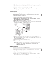
Fan, Power/LED switch, Swing the CD-ROM drive cage up.
 |
UPC - 087944665854
View all IBM 621410U manuals
Add to My Manuals
Save this manual to your list of manuals |
Page 96 highlights
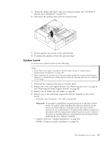
Fan To remove the fan, do the following: Note: Read "Before you begin" on page 41 and the safety notices at "Safety notices (multi-lingual translations)" on page 135. 1. Power-off the computer and remove external cables. 2. Remove the cover and support bracket (see "Removing the cover" on page 45 and "Removing the frame support bracket" on page 46). 3. Remove the air baffle (see "Air baffle" on page 87). 4. Disconnect the fan cable from the system board. 5. For the desktop model, push in on the two tabs on the front of the chassis to release the fan. 6. Pull the fan up and out of the chassis. 7. To install the rear fan, reverse the previous steps. Power/LED switch To remove the power/LED switch, do the following: Note: Read "Before you begin" on page 41 and the safety notices at "Safety notices (multi-lingual translations)" on page 135. 1. Power-off the computer and remove external cables. 2. Remove the cover and support bracket (see "Removing the cover" on page 45 and "Removing the frame support bracket" on page 46). 3. Swing the CD-ROM drive cage up. 4. Disengage the lower tab of the power/LED switch by pressing upward on the lower tab of the power/LED switch until it comes loose. Note: It may be necessary to use the tip of a screwdriver to disengage the lower tab. 5. Push inward on the two tabs of the top section of the power/LED switch until it pops free of the chassis; then, remove it from the computer, making sure that the cable follows freely. 88 Hardware Maintenance Manual: IBM IntelliStation E Pro Type 6204 and Type 6214
-
 1
1 -
2
-
3
-
4
-
5
-
6
-
7
-
8
-
9
-
10
-
11
-
12
-
13
-
14
-
15
-
16
-
17
-
18
-
19
-
20
-
21
-
22
-
23
-
24
-
25
-
26
-
27
-
28
-
29
-
30
-
31
-
32
-
33
-
34
-
35
-
36
-
37
-
38
-
39
-
40
-
41
-
42
-
43
-
44
-
45
-
46
-
47
-
48
-
49
-
50
-
51
-
52
-
53
-
54
-
55
-
56
-
57
-
58
-
59
-
60
-
61
-
62
-
63
-
64
-
65
-
66
-
67
-
68
-
69
-
70
-
71
-
72
-
73
-
74
-
75
-
76
-
77
-
78
-
79
-
80
-
81
-
82
-
83
-
84
-
85
-
86
-
87
-
88
-
89
-
90
-
 91
91 -
 92
92 -
 93
93 -
 94
94 -
 95
95 -
 96
96 -
 97
97 -
 98
98 -
 99
99 -
 100
100 -
 101
101 -
102
-
103
-
104
-
105
-
106
-
107
-
108
-
109
-
110
-
111
-
112
-
113
-
114
-
115
-
116
-
117
-
118
-
119
-
120
-
121
-
122
-
123
-
124
-
125
-
126
-
127
-
128
-
129
-
130
-
131
-
132
-
133
-
134
-
135
-
136
-
137
-
138
-
139
-
140
-
141
-
142
-
143
-
144
-
145
-
146
-
147
-
148
-
149
-
150
-
151
-
152
-
153
-
154
-
155
-
156
-
157
-
158
-
159
-
160
-
161
-
162
-
163
-
164
-
165
-
166
-
167
-
168
-
169
-
170
-
171
-
172
-
173
-
174
-
175
-
176
 |
 |
