IBM 621410U Hardware Maintenance Manual - Page 110
System board, processor. If the adhesive material on the processor will
 |
UPC - 087944665854
View all IBM 621410U manuals
Add to My Manuals
Save this manual to your list of manuals |
Page 110 highlights
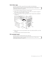
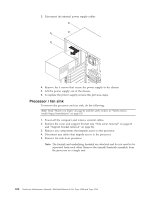
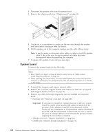
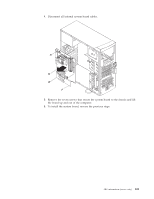
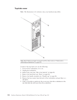
3. Disconnect the speaker cable from the system board. 4. Remove the adapter guide (see "Adapter guide" on page 93). 5. Use the tip of a screwdriver to gently pry the two tabs through the notches until the speaker disengages from the chassis. 6. Lift the speaker out of the computer, making sure the cable follows freely. Note: It may be easier to disconnect other cables in order to reach the speaker cable. If this is the case, be sure to reattach all cables that were disconnected before reassembling the computer. 7. To replace the speaker, reverse the previous steps. System board To remove the system board, do the following: Notes: 1. Read "Before you begin" on page 41 and the safety notices at "Safety notices (multi-lingual translations)" on page 135. 2. When replacing the system board, you must either update the system with the latest firmware or restore the pre-existing firmware that the customer provides on a diskette or CD image. 1. Power-off the computer and remove external cables. 2. Remove the cover and support bracket (see "Side cover removal" on page 63 and "Support bracket removal" on page 64). 3. Remove any of the following components that are installed on the system board: v Processor (see "Processor / fan sink" on page 100). Important: If you plan to reinstall an existing processor to the new system board, be careful when handling the adhesive material on the processor. If the adhesive material on the processor will be reused, do not contaminate it. If replacement adhesive material is provided with the replacement system board, be sure to remove all traces of existing adhesive material from the processor before applying the new adhesive material. v Adapter cards (see "Adapter installation" on page 66). v DIMMs (see "Memory module installation" on page 74). 102 Hardware Maintenance Manual: IBM IntelliStation E Pro Type 6204 and Type 6214
-
 1
1 -
2
-
3
-
4
-
5
-
6
-
7
-
8
-
9
-
10
-
11
-
12
-
13
-
14
-
15
-
16
-
17
-
18
-
19
-
20
-
21
-
22
-
23
-
24
-
25
-
26
-
27
-
28
-
29
-
30
-
31
-
32
-
33
-
34
-
35
-
36
-
37
-
38
-
39
-
40
-
41
-
42
-
43
-
44
-
45
-
46
-
47
-
48
-
49
-
50
-
51
-
52
-
53
-
54
-
55
-
56
-
57
-
58
-
59
-
60
-
61
-
62
-
63
-
64
-
65
-
66
-
67
-
68
-
69
-
70
-
71
-
72
-
73
-
74
-
75
-
76
-
77
-
78
-
79
-
80
-
81
-
82
-
83
-
84
-
85
-
86
-
87
-
88
-
89
-
90
-
91
-
92
-
93
-
94
-
95
-
96
-
97
-
98
-
99
-
100
-
101
-
102
-
103
-
104
-
 105
105 -
 106
106 -
 107
107 -
 108
108 -
 109
109 -
 110
110 -
 111
111 -
 112
112 -
 113
113 -
 114
114 -
 115
115 -
116
-
117
-
118
-
119
-
120
-
121
-
122
-
123
-
124
-
125
-
126
-
127
-
128
-
129
-
130
-
131
-
132
-
133
-
134
-
135
-
136
-
137
-
138
-
139
-
140
-
141
-
142
-
143
-
144
-
145
-
146
-
147
-
148
-
149
-
150
-
151
-
152
-
153
-
154
-
155
-
156
-
157
-
158
-
159
-
160
-
161
-
162
-
163
-
164
-
165
-
166
-
167
-
168
-
169
-
170
-
171
-
172
-
173
-
174
-
175
-
176
 |
 |
