Kyocera FS-9120DN FS-9120DN/9520DN Operation Guide Rev-2 - Page 103
Appendix B Host Computer Interface, 1. Parallel Interface, 1.1 Parallel Interface Communication Modes
 |
View all Kyocera FS-9120DN manuals
Add to My Manuals
Save this manual to your list of manuals |
Page 103 highlights
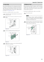
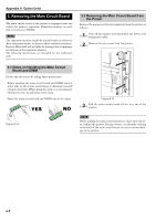
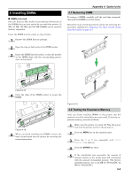
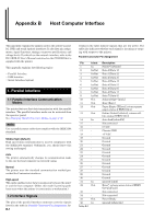
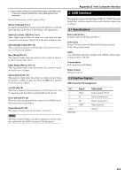
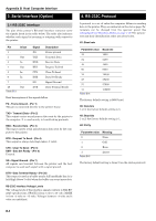
Appendix B Host Computer Interface This appendix explains the signals used in the printer's parallel, USB, and serial (option) interfaces. It also lists pin assignments, signal functions, timings, connector specifications, and voltage levels. For details on the network interface, refer to the IB-21E/IB-22 User's Manual contained on the CD-ROM that is supplied with the printer. This appendix explains the following topics: • Parallel Interface • USB Interface • Serial Interface (option) 1. Parallel Interface 1.1 Parallel Interface Communication Modes The printer features fast data transmission with the parallel interface. The parallel interface mode can be activated from the operator panel. See Changing Parallel Interface Modes on page 3-19. NOTE Use a parallel printer cable that complies with the IEEE1284 standard. Nibble (high) [default] High speed data communication is used in compliance with the IEEE1284 standard. Ordinarily, you should leave this setting unchanged. Auto The printer automatically changes its communication mode to the one the host computer is currently using. Normal The printer uses the standard communication method prescribed for Centronics interfaces. High-speed This mode enables faster data transmission between the printer and the host computer. (Select this mode if printing problems occur when the printer is connected to a workstation.) 1.2 Interface Signals The pins of the parallel interface connector carry the signals listed in the table in Parallel Connector Pin Assignment. AsB-1 terisks in the table indicate signals that are low active. The table also indicates whether each signal is incoming or outgoing with respect to the printer. Parallel Connector Pin Assignment Pin In/out 1 In 2 In/Out 3 In/Out 4 In/Out 5 In/Out 6 In/Out 7 In/Out 8 In/Out 9 In/Out 10 Out 11 Out 12 Out 13 Out 14 In 15 - 16 - 17 - 18 - 19 - 20 - 21 - 22 - 23 - 24 - 25 - 26 - 27 - 28 - 29 - 30 - 31 In 32 Out 33 - 34 - 35 Out 36 In Table B-1 Description Strobe* [nStrobe] Data 0 [Data 1] Data 1 [Data 2] Data 2 [Data 3] Data 3 [Data 4] Data 4 [Data 5] Data 5 [Data 6] Data 6 [Data 7] Data 7 [Data 8] Acknowledge* [nAck] Busy [Busy] Paper Empty [PError], returns paper empty status if FRPO O2=2 Online (Select) [nSelect], returns offline status if FRPO O2=2 Auto-feed [nAutoFd] Not connected 0 V DC Chassis GND +5 V DC Ground Ground Ground Ground Ground Ground Ground Ground Ground Ground Ground Ground Ignored [nInit] Error*, returns error status if FRPO O2=2 [nFault] Not connected Not connected Power Ready Ignored [nSelectIn]
-
 1
1 -
2
-
3
-
4
-
5
-
6
-
7
-
8
-
9
-
10
-
11
-
12
-
13
-
14
-
15
-
16
-
17
-
18
-
19
-
20
-
21
-
22
-
23
-
24
-
25
-
26
-
27
-
28
-
29
-
30
-
31
-
32
-
33
-
34
-
35
-
36
-
37
-
38
-
39
-
40
-
41
-
42
-
43
-
44
-
45
-
46
-
47
-
48
-
49
-
50
-
51
-
52
-
53
-
54
-
55
-
56
-
57
-
58
-
59
-
60
-
61
-
62
-
63
-
64
-
65
-
66
-
67
-
68
-
69
-
70
-
71
-
72
-
73
-
74
-
75
-
76
-
77
-
78
-
79
-
80
-
81
-
82
-
83
-
84
-
85
-
86
-
87
-
88
-
89
-
90
-
91
-
92
-
93
-
94
-
95
-
96
-
97
-
 98
98 -
 99
99 -
 100
100 -
 101
101 -
 102
102 -
 103
103 -
 104
104 -
 105
105 -
 106
106 -
 107
107 -
 108
108 -
109
-
110
-
111
-
112
-
113
-
114
-
115
 |
 |